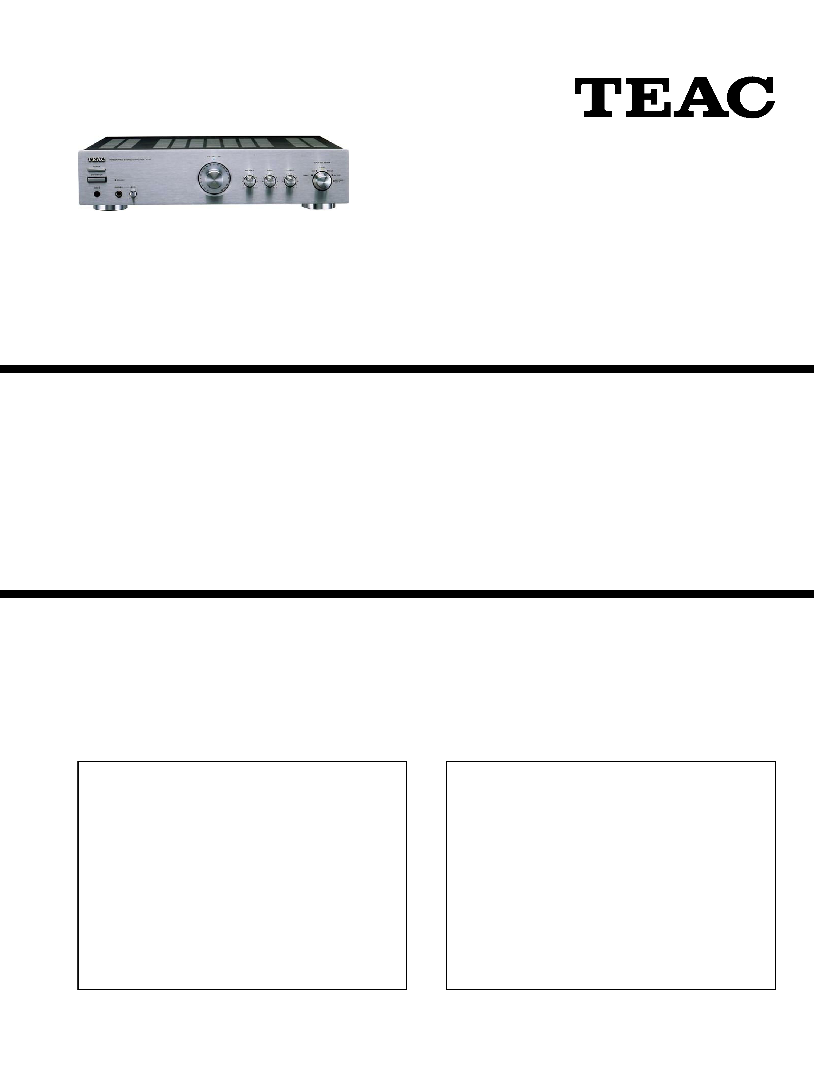
TEAC A-1 D Service Manual

Cover page of TEAC A-1 D Service Manual

Service Manual for TEAC A-1 D, downloadable as a PDF file.

We also have owner's manual to this model.

Manual details

  • Immediate download after payment.
  • Delivered as a PDF file.
  • The manual has 25 pages
  • File size: 1.15 MB
  • Available language versions: English
  • Different language versions may vary sligthly in file size and page count.

We guarantee that...

  • our manuals are complete,
  • the manual includes circuit diagrams,
  • our manuals are checked with antivirus,
  • We'll issue refund if the manual is damaged, incomplete or unreadable (our refund policy)

Sample pages

Thumbnail of page 1Thumbnail of page 2Thumbnail of page 3Thumbnail of page 4
Thumbnail of page 5Thumbnail of page 6Thumbnail of page 7Thumbnail of page 8
Thumbnail of page 9
background image
A
A-- 11 D
D
SERVICE MANUAL
Integrated Stereo Amplifier
Effective : December, 2002
S-0074A
CONTENTS
1 SPECIFICATIONS
2
2 ADJUSTMENTS
3
3 EXPLODED VIEWS AND PARTS LIST
4
4 PC BOARDS AND PARTS LIST
6
5 INCLUDED ACCESSORIES
10
NOTES
PC boards shown are viewed from parts side.
The parts with no reference number or no parts number in the
exploded views are not supplied.
As regards the resistors and capacitors, refer to the circuit diagrams
contained in this manual.
£
Parts marked with this sign are safety critical components. They
must be replaced with identical components - refer to the appropriate
parts list and ensure exact replacement.
Parts of [ ] mark can be used only with the version designated.
£
background image
1 SPECIFICATIONS
2
Amplifier Section
Power output ........................ 50 W +50 W (8, 1kHz, 0.1% THD)
S/N Ratio ........................................................ LINE : 85dB (IHF-A)
Input Sensitivity/Impedance .......................... LINE : 300mV/47k
Frequency Response ...................................... LINE : 20Hz~60kHz
Tone Control .............................................. BASS : ±10dB (100Hz)
TREBLE : ±10dB (10kHz)
General
Power Requirement .................................................... 230V, 50Hz
Power Consumption ............................................................ 160 W
Dimensions (W x H x D) ................................ 435 x 102 x 370mm
Weight (Net) ........................................................................ 7.7 kg
Standard Accessory ........................ Remote Control Unit (RC-1D)
(Batteries are not included)
Design and specifications are subject to change without notice.
background image
2 ADJUSTMENTS
3
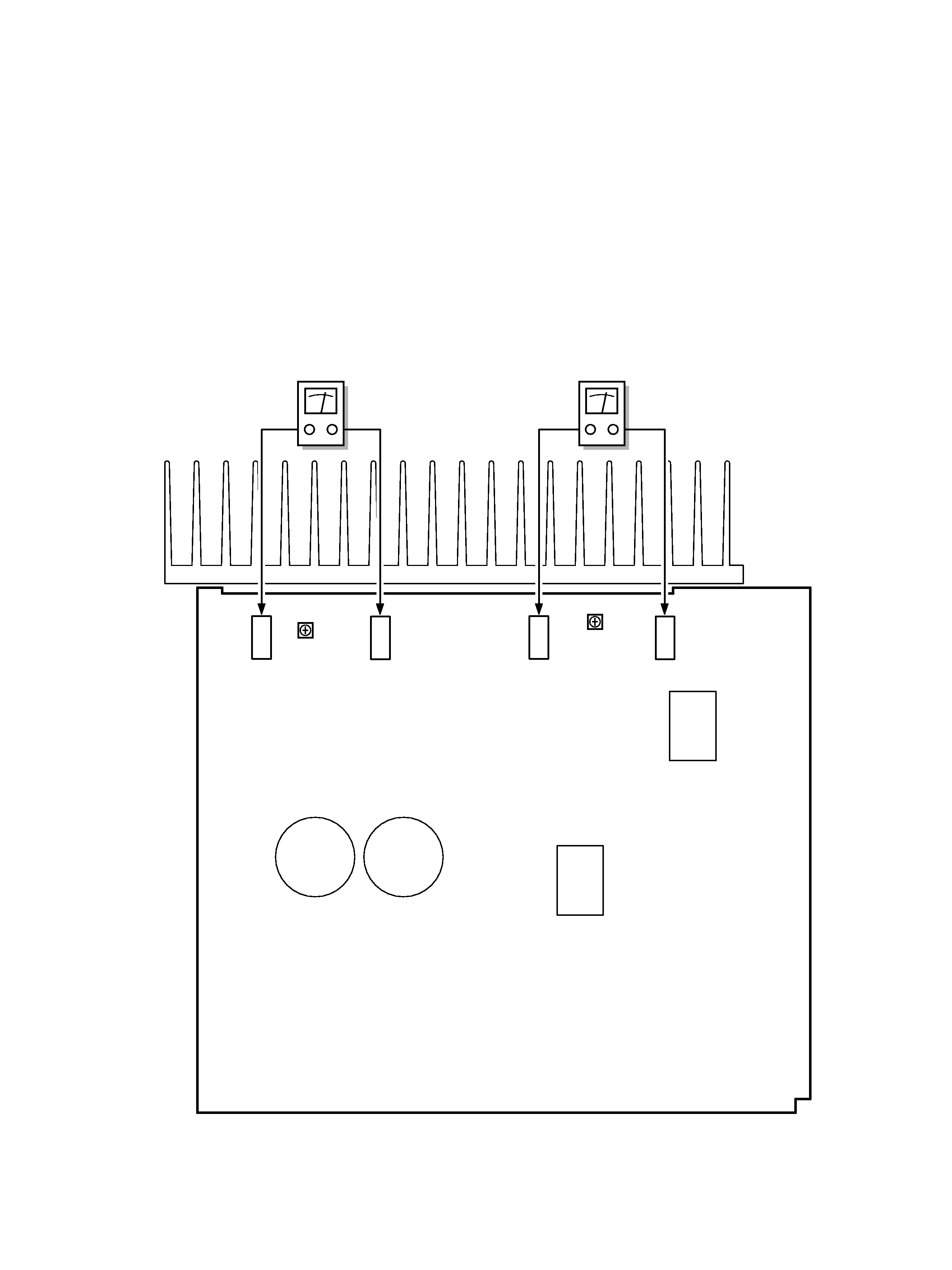
Bias Current Adjustment
1. Set the VOLUME control to " ".
2. Set the POWER switch to ON and wait for 10 minutes for
preheating.
3. Adjust TVR1 so that the voltage between R142 (heat sink side)
and R141 (heat sink side) on AMP PCB becomes 10 1mV.
4. In the same way, adjust TVR2 so that the voltage between
R143 (heat sink side) and R144 (heat sink side) becomes 10
1mV.
R142
R141
R143
R144
TVR2
TVR1
AMP PCB
DC voltmeter
DC voltmeter
background image
4
1
2
3
4
6
7
8
9
0
q
w
e
r
t
y
u
i
o
p
a
s
d
f
g
h
j
k
l
;
z
x
c
v
b
n
c
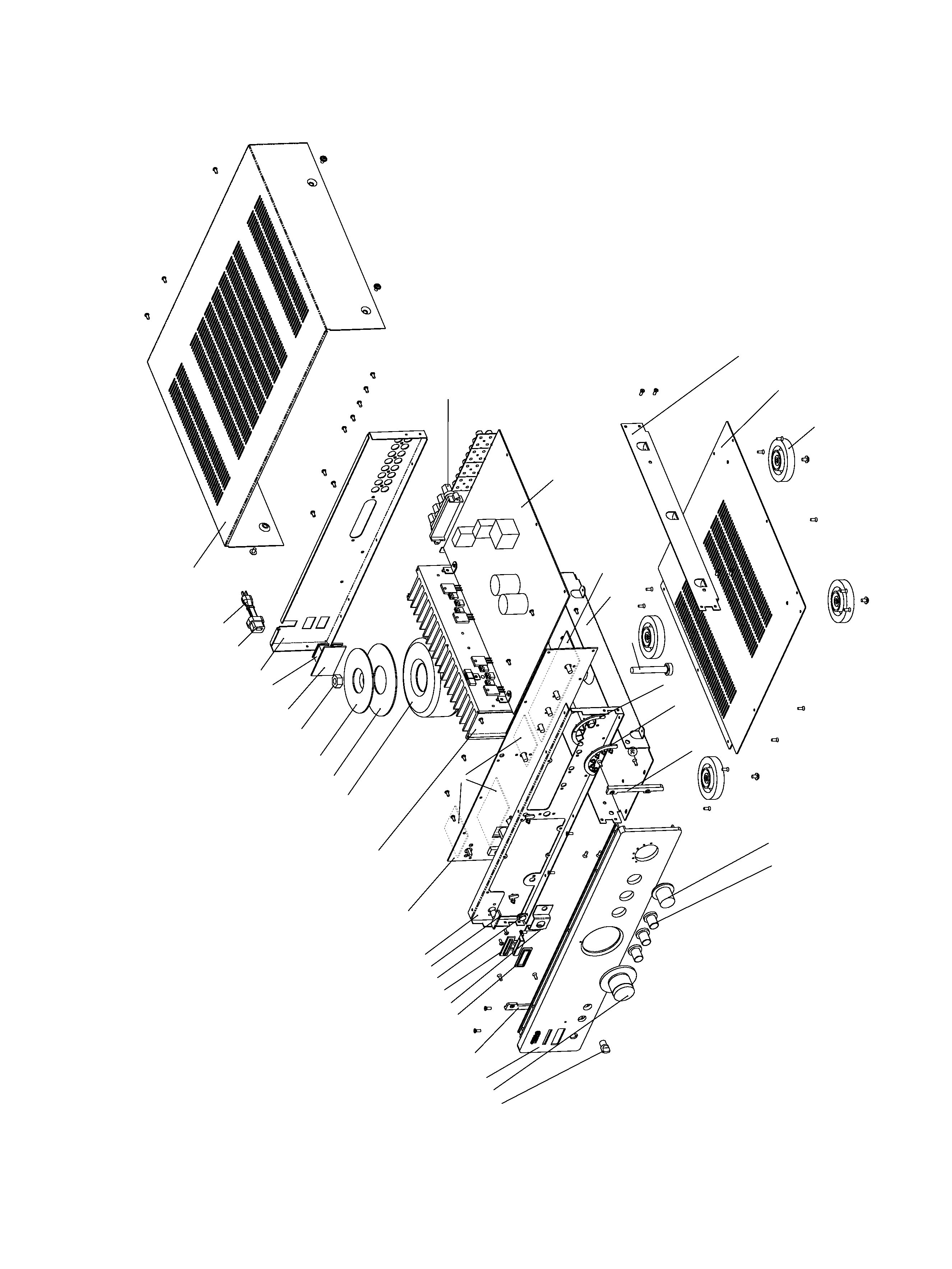
3 EXPLODED VIEWS AND PARTS LIST
background image
5
EXPLODED VIEW LIST
£
£
£
£
£
£
£
£
£
£
£
£
£

Reviews

There are no reviews of this manual yet.