ORDER NO.
PIONEER CORPORATION 4-1, Meguro 1-chome, Meguro-ku, Tokyo 153-8654, Japan
PIONEER ELECTRONICS (USA) INC. P.O. Box 1760, Long Beach, CA 90801-1760, U.S.A.
PIONEER EUROPE NV Haven 1087, Keetberglaan 1, 9120 Melsele, Belgium
PIONEER ELECTRONICS ASIACENTRE PTE. LTD. 253 Alexandra Road, #04-01, Singapore 159936
PIONEER CORPORATION 2008
S-CX505-K
RRV3802
T-ZZR JULY 2008 Printerd in Japan
SPEAKER SYSTEM
S-CX505-K
/XTM/E
S-CX505-K /XTM/CN5
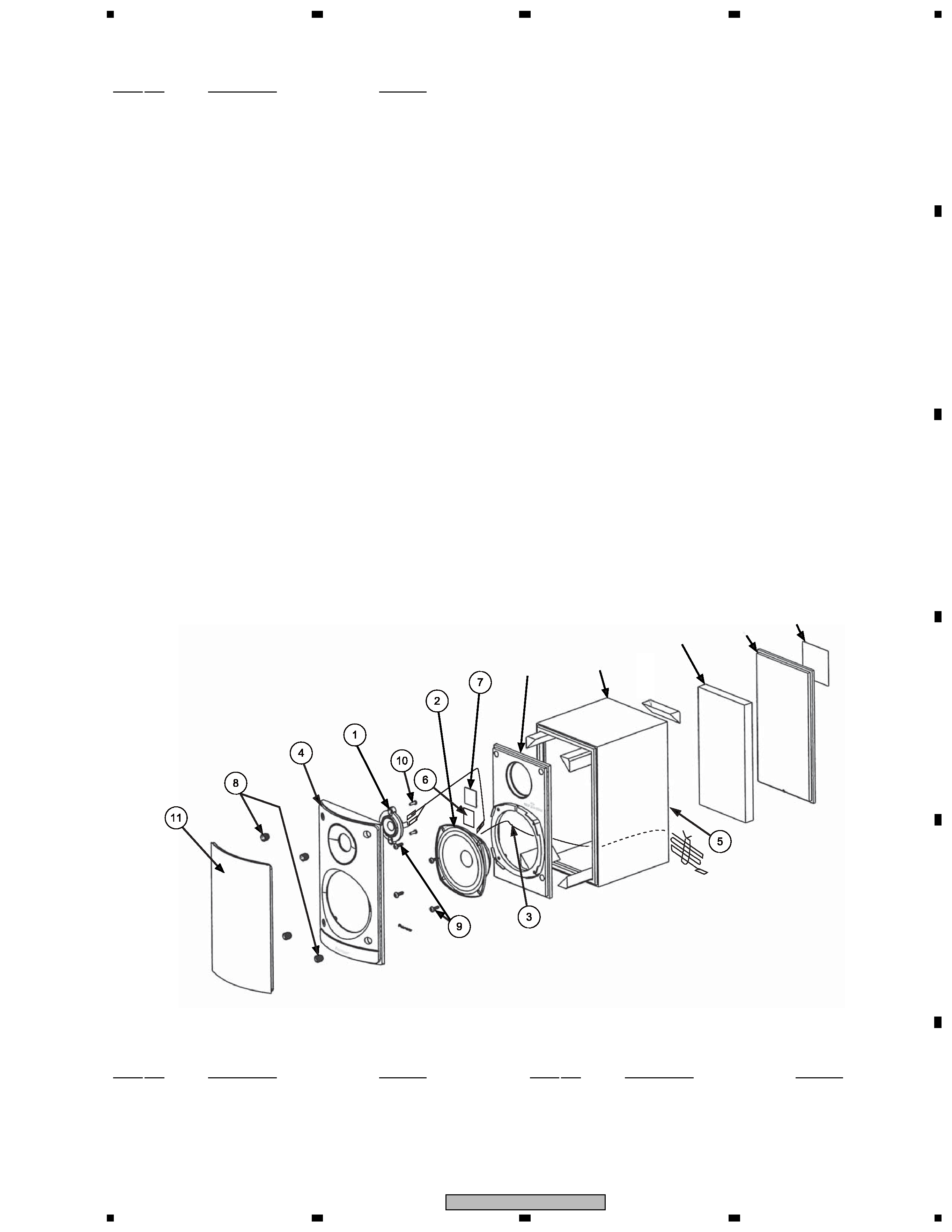
1.1 FRONT SPEAKER
The grille is attached to the cosmetic baffle by 4 catches. Detach
by pulling it toward you.
The cosmetic baffle is attached to the baffle by press fitting. To
detach it, pry it open by inserting a flat blade screwdriver into
lower side.
The woofer is attached to the baffle by 4 external screws. The
tweeter is attached to the cosmetic baffle by 2 internal screws.
To detach the speaker unit, first remove the cosmetic baffle.
Next unfasten those screws. Then remove the connecting cord.
When attaching the woofer, face its terminal foward the upward.
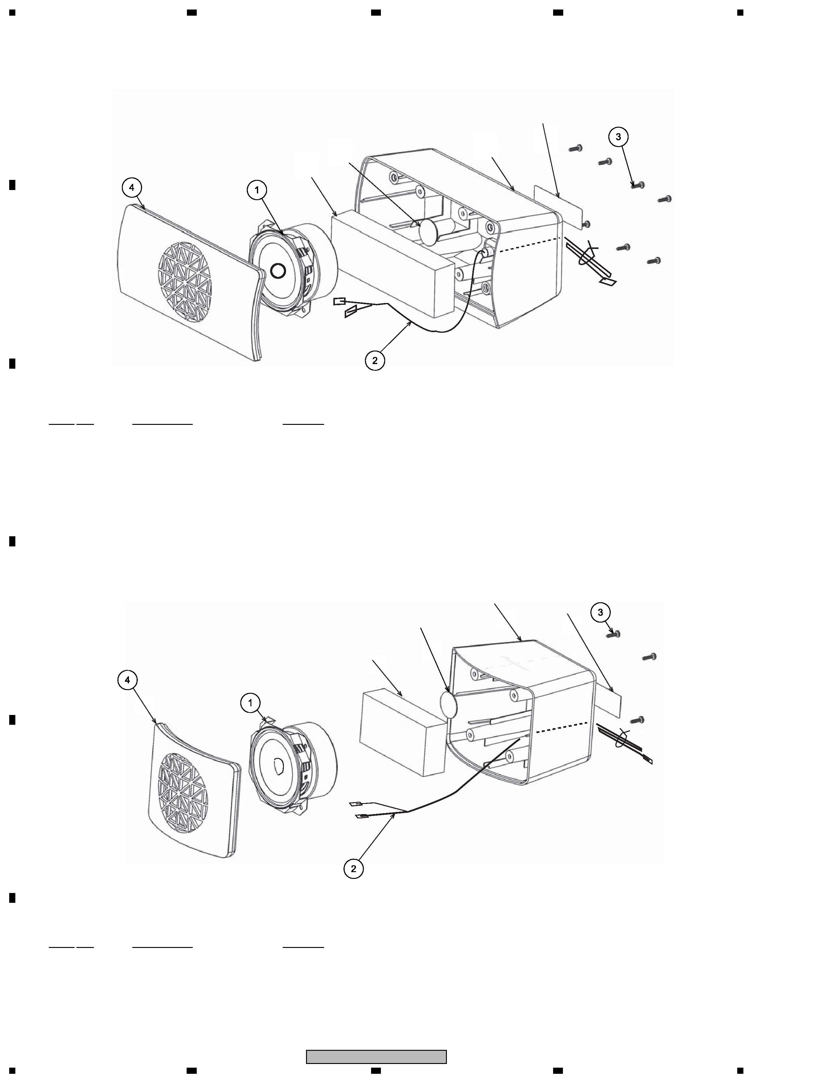
1.2 CENTER SPEAKER
The grille assy(center) is attached to the cabinet by 8 external
screws. To detach it, unfasten those screws.
The speaker unit is attached together with the grille assy to the
cabinet by 4 external screws. To detach it, first unfasten those
screws. Then remove the connecting cord.
1.3 SURROUND SPEAKER
The grille assy(surround) is attached to the cabinet by 4 external
screws. To detach it, unfasten those screws.
The speaker unit is attached together with the grille assy to the
cabinet by 4 external screws. To detach it, first unfasten those
screws. Then remove the connecting cord.
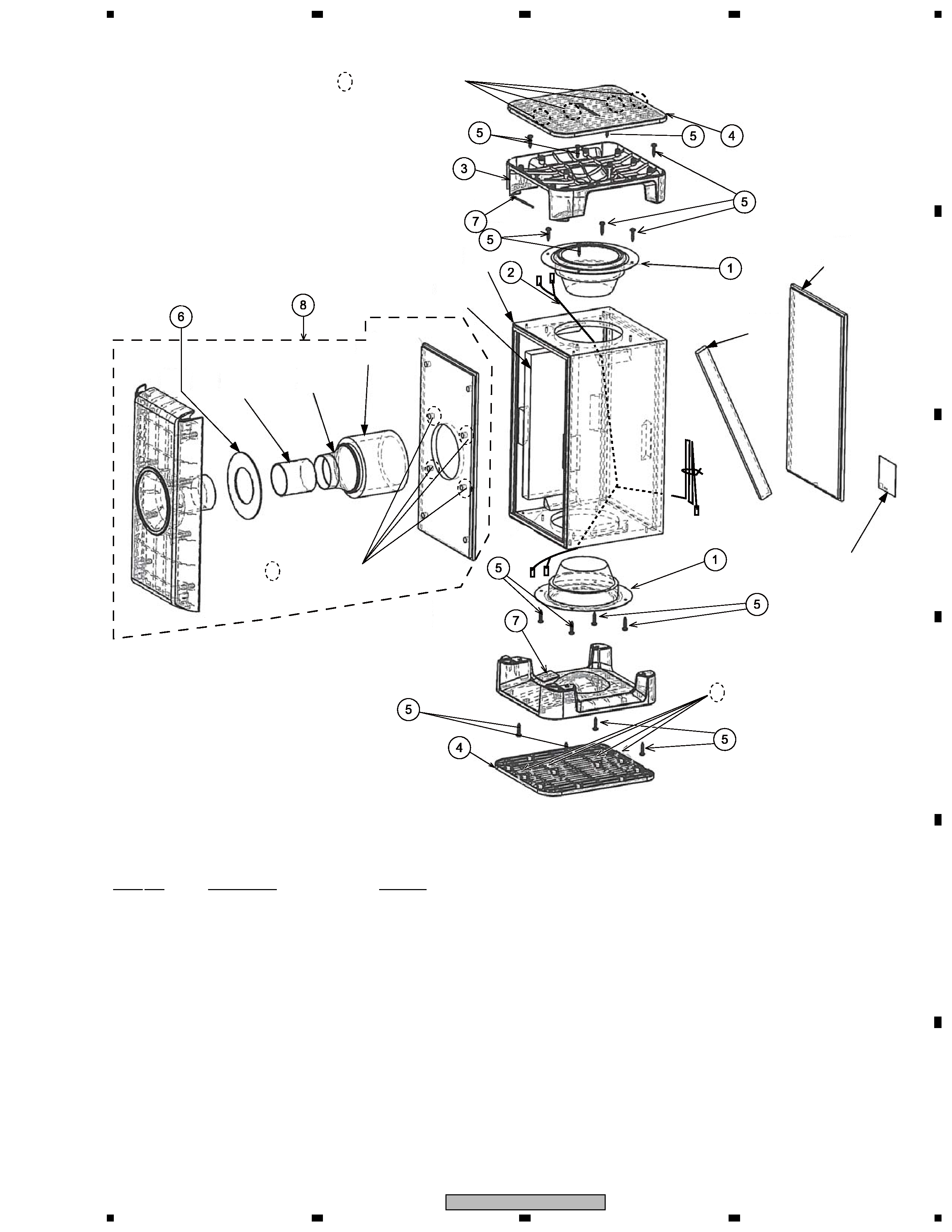
1.4 SUBWOOFER
The base cover is attached to the basc by press fitting. To detach
it, pry it open by inserting aflat blade screw driver into back side
slot.
The base is attached to the cabinet by 4 external screws. When
detatch it, first remove the base cover. Next unfasten those
screws. The speaker unit is attached to the cabinet board by 4
external screws. To detach it, unfasten those screws.
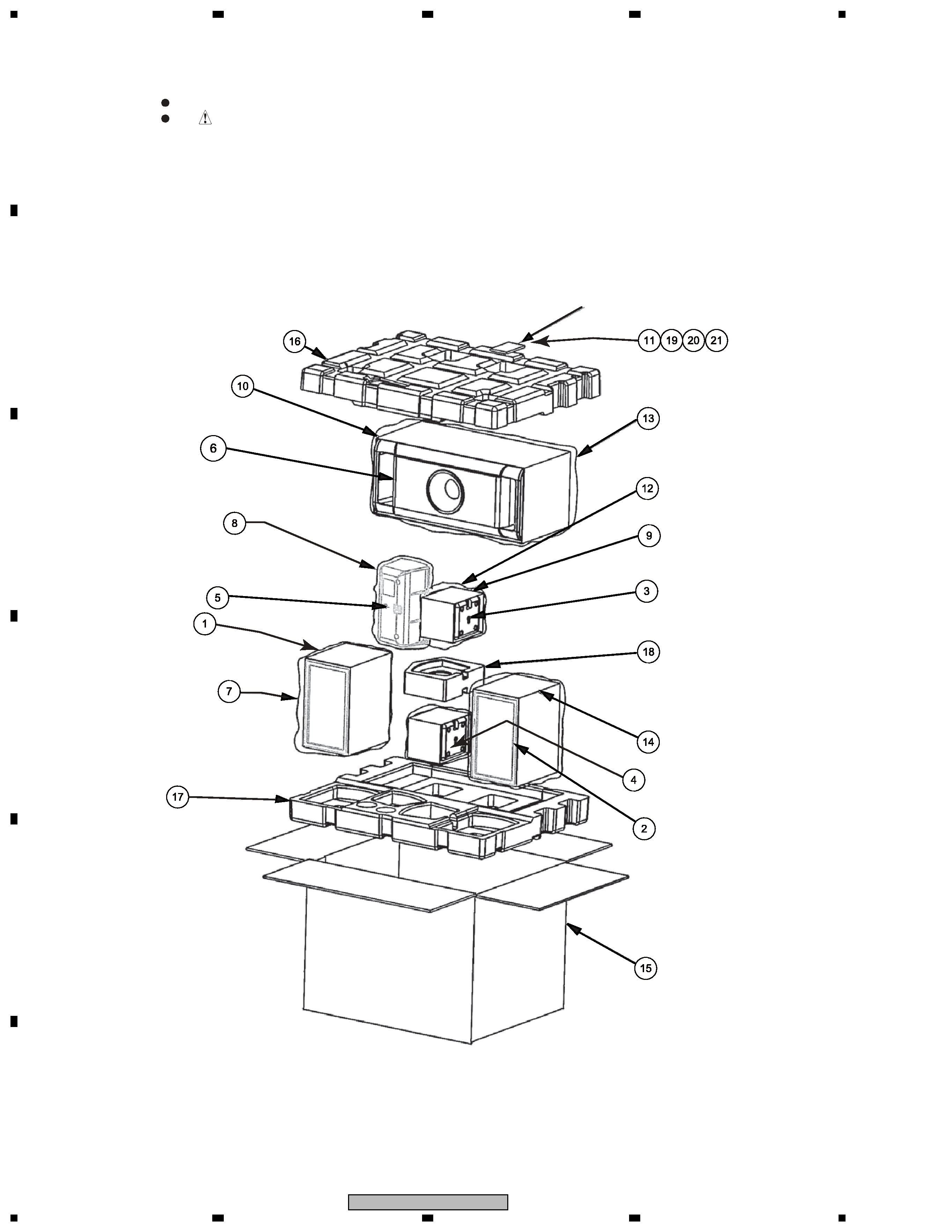
1. REASSEMBLEY AND DISASSEMBLY PRECAUTION