PIONEER DVR-543H-S/KUCXV Service Manual

Cover page of PIONEER DVR-543H-S/KUCXV Service Manual

Service Manual for PIONEER DVR-543H-S/KUCXV, downloadable as a PDF file.

We also have owner's manual to this model.

Manual details

  • Immediate download after payment.
  • Delivered as a PDF file.
  • The manual has 128 pages
  • File size: 11.15 MB
  • Available language versions: English
  • Different language versions may vary sligthly in file size and page count.

We guarantee that...

  • our manuals are complete,
  • the manual includes circuit diagrams,
  • our manuals are checked with antivirus,
  • We'll issue refund if the manual is damaged, incomplete or unreadable (our refund policy)

Sample pages

Thumbnail of page 1Thumbnail of page 2Thumbnail of page 3Thumbnail of page 4
Thumbnail of page 5Thumbnail of page 6Thumbnail of page 7Thumbnail of page 8
Thumbnail of page 9
background image
ORDER NO.
PIONEER CORPORATION 4-1, Meguro 1-chome, Meguro-ku, Tokyo 153-8654, Japan
PIONEER ELECTRONICS (USA) INC. P.O. Box 1760, Long Beach, CA 90801-1760, U.S.A.
PIONEER EUROPE NV Haven 1087, Keetberglaan 1, 9120 Melsele, Belgium
PIONEER ELECTRONICS ASIACENTRE PTE. LTD. 253 Alexandra Road, #04-01, Singapore 159936
PIONEER CORPORATION 2006
DVR-640H-S
RRV3376
DVD RECORDER
DVR-640H-S
DVR-543H-S
DVR-540H-S
THIS MANUAL IS APPLICABLE TO THE FOLLOWING MODEL(S) AND TYPE(S).
Model
Type
Power Requirement
Region No.
Serial No.
Please confirm 3rd & 4th
alphabetical letters.
DVR-640H-S
KUCXV
AC120 V
1
&&DL######$$
DVR-543H-S
KUCXV
AC120 V
1
&&DL######$$
DVR-540H-S
KUCXV
AC120 V
1
&&DL######$$
÷ When servicing this model, some service procedures may reset the customer settings
to the factory default settings. Make sure to explain this to the customer.
An HDD (Hard Disc Drive) is mounted in this product.
The HDD is a precision instrument very vulnerable to shock and electrostatic charges. Please read
"7.3 Cautions on Handling the HDD" in this manual and exercise sufficient caution when handling the
HDD itself, as well as the product with the HDD built in.
When an HDD becomes defective and inoperable, restoration of the user's data recorded on the HDD,
or copying of the user's recorded data to other media (such as a new HDD) is totally impossible.
Before servicing, OBTAIN THE USER'S PRIOR CONSENT to that effect.
The user must be made aware that all recorded data are deleted if the HDD is intialized.
For details, refer to "Important Check Points for Good Servicing" .
T-ZZV APR. 2006 printed in Japan
background image
DVR-640H-S
2
12
34
12
3
4
C
D
F
A
B
E
SAFETY INFORMATION
This service manual is intended for qualified service technicians; it is not meant for the casual
do-it-yourselfer. Qualified technicians have the necessary test equipment and tools, and have been
trained to properly and safely repair complex products such as those covered by this manual.
Improperly performed repairs can adversely affect the safety and reliability of the product and may
void the warranty. If you are not qualified to perform the repair of this product properly and safely, you
should not risk trying to do so and refer the repair to a qualified service technician.
WARNING
This product contains lead in solder and certain electrical parts contain chemicals which are known to the state of California to
cause cancer, bir th defects or other reproductive harm.
Health & Safety Code Section 25249.6 ­ Proposition 65
NOTICE
(FOR CANADIAN MODEL ONLY)
Fuse symbols
(fast operating fuse)
and/or
(slow operating fuse) on PCB indicate that replacement
parts must be of identical designation.
REMARQUE
(POUR MODÈLE CANADIEN SEULEMENT)
Les symboles de fusible
(fusible de type rapide)
et/ou
(fusible de type lent) sur CCI indiquent que
les pièces de remplacement doivent avoir la même désignation.
ANY MEASUREMENTS NOT WITHIN THE
LIMITS OUTLINED ABOVE ARE INDICATIVE
OF A POTENTIAL SHOCK HAZARD AND
MUST BE CORRECTED BEFORE RETURN-
ING THE APPLIANCE TO THE CUSTOMER.
2. PRODUCT SAFETY NOTICE
Many electrical and mechanical parts in the appliance
have special safety related character istics. These are
often not evident
from visual
inspection nor the
protection afforded by them necessarily can be obtained
by using replacement components rated for voltage,
wattage, etc. Replacement parts which have these
special safety characteristics are identified in this
Service Manual.
Electrical components having such features are
identified by marking with a
on the schematics and
on the parts list in this Service Manual.
The use of a substitute replacement component which
does not have the same safety characteristics as the
PIONEER recommended replacement one, shown in the
parts list in this Service Manual, may create shock, fire,
or other hazards.
Product Safety is continuously under review and new
instructions are issued from time to time. For the latest
information, always consult the current PIONEER
Service Manual. A subscription to, or
additional copies
of, PIONEER Service Manual may be obtained at a
nominal charge from PIONEER.
(FOR USA MODEL ONLY)
1. SAFETY PRECAUTIONS
The following check should be performed for the
continued protection of the customer and service
technician.
LEAKAGE CURRENT CHECK
Measure leakage current to a known earth ground
(water pipe, conduit, etc.) by connecting a leakage
current tester such as Simpson Model 229-2 or
equivalent between the earth ground and all exposed
metal parts of the appliance (input/output terminals,
screwheads, metal overlays, control shaft, etc.). Plug
the AC line cord of the appliance directly into a 120V
AC 60 Hz outlet and turn the AC power switch on. Any
current measured must not exceed 0.5 mA.
Device
under
test
Leakage
current
tester
Earth
ground
Reading should
not be above
0.5 mA
Also test with
plug reversed
(Using AC adapter
plug as required)
Test all
exposed metal
surfaces
AC Leakage Test
background image
DVR-640H-S
3
56
78
56
7
8
C
D
F
A
B
E
LABEL CHECK
IMPORTANT
THIS PIONEER APPARATUS CONTAINS
LASER OF CLASS 1.
SERVICING OPERATION OF THE APPARATUS
SHOULD BE DONE BY A SPECIALLY
INSTRUCTED PERSON.
CLAMP signals for detecting the loading state are detected
by the drive CPUs, and the design prevents laser diode
oscillation when the CLAMP signal turns OFF.
In normal operation, if no disc is clamped, the laser diode
oscillation is disabled.
However, the interlock does not always operate in the test
mode.
2. When the cover is opened, close viewing of the objective
lens with the naked eye will cause exposure to a Class 3A
laser beam.
Additional Laser Caution
1. The ON/OFF(ON:low level,OFF:high level) status of the
LASER DIODE CHARACTERISTICS
MAXIMUM OUTPUT POWER: 100 mW
WAVELENGTH: 654nm to 662 nm
LASER DIODE CHARACTERISTICS
MAXIMUM OUTPUT POWER: 5 mW
WAVELENGTH: 770nm to 810 nm
HD
D/D
VD
HD
DH
DD
DV
D
VRW2262
background image
DVR-640H-S
4
12
34
12
3
4
C
D
F
A
B
E
[Important Check Points for Good Servicing]
In this manual, procedures that must be performed during repairs are marked with the below symbol.
Please be sure to confirm and follow these procedures.
1. Product safety
Please conform to product regulations (such as safety and radiation regulations), and maintain a safe servicing environment by
following the safety instructions described in this manual.
1 Use specified parts for repair.
Use genuine parts. Be sure to use important parts for safety.
2 Do not perform modifications without proper instructions.
Please follow the specified safety methods when modification(addition/change of parts) is required due to interferences such as
radio/TV interference and foreign noise.
3 Make sure the soldering of repaired locations is properly performed.
When you solder while repairing, please be sure that there are no cold solder and other debris.
Soldering should be finished with the proper quantity. (Refer to the example)
4 Make sure the screws are tightly fastened.
Please be sure that all screws are fastened, and that there are no loose screws.
5 Make sure each connectors are correctly inserted.
Please be sure that all connectors are inserted, and that there are no imperfect insertion.
6 Make sure the wiring cables are set to their original state.
Please replace the wiring and cables to the original state after repairs.
In addition, be sure that there are no pinched wires, etc.
7 Make sure screws and soldering scraps do not remain inside the product.
Please check that neither solder debris nor screws remain inside the product.
8 There should be no semi-broken wires, scratches, melting, etc. on the coating of the power cord.
Damaged power cords may lead to fire accidents, so please be sure that there are no damages.
If you find a damaged power cord, please exchange it with a suitable one.
9 There should be no spark traces or similar marks on the power plug.
When spark traces or similar marks are found on the power supply plug, please check the connection and advise on secure
connections and suitable usage. Please exchange the power cord if necessary.
0 Safe environment should be secured during servicing.
When you perform repairs, please pay attention to static electricity, furniture, household articles, etc. in order to prevent injuries.
Please pay attention to your surroundings and repair safely.
2. Adjustments
To keep the original performance of the products, optimum adjustments and confirmation of characteristics within specification.
Adjustments should be performed in accordance with the procedures/instructions described in this manual.
4. Cleaning
For parts that require cleaning, such as optical pickups, tape deck heads, lenses and mirrors used in projection monitors, proper
cleaning should be performed to restore their performances.
3. Lubricants, Glues, and Replacement parts
Use grease and adhesives that are equal to the specified substance.
Make sure the proper amount is applied.
5. Shipping mode and Shipping screws
To protect products from damages or failures during transit, the shipping mode should be set or the shipping screws should be
installed before shipment. Please be sure to follow this method especially if it is specified in this manual.
background image
DVR-640H-S
5
56
78
56
7
8
C
D
F
A
B
E
CONTENTS
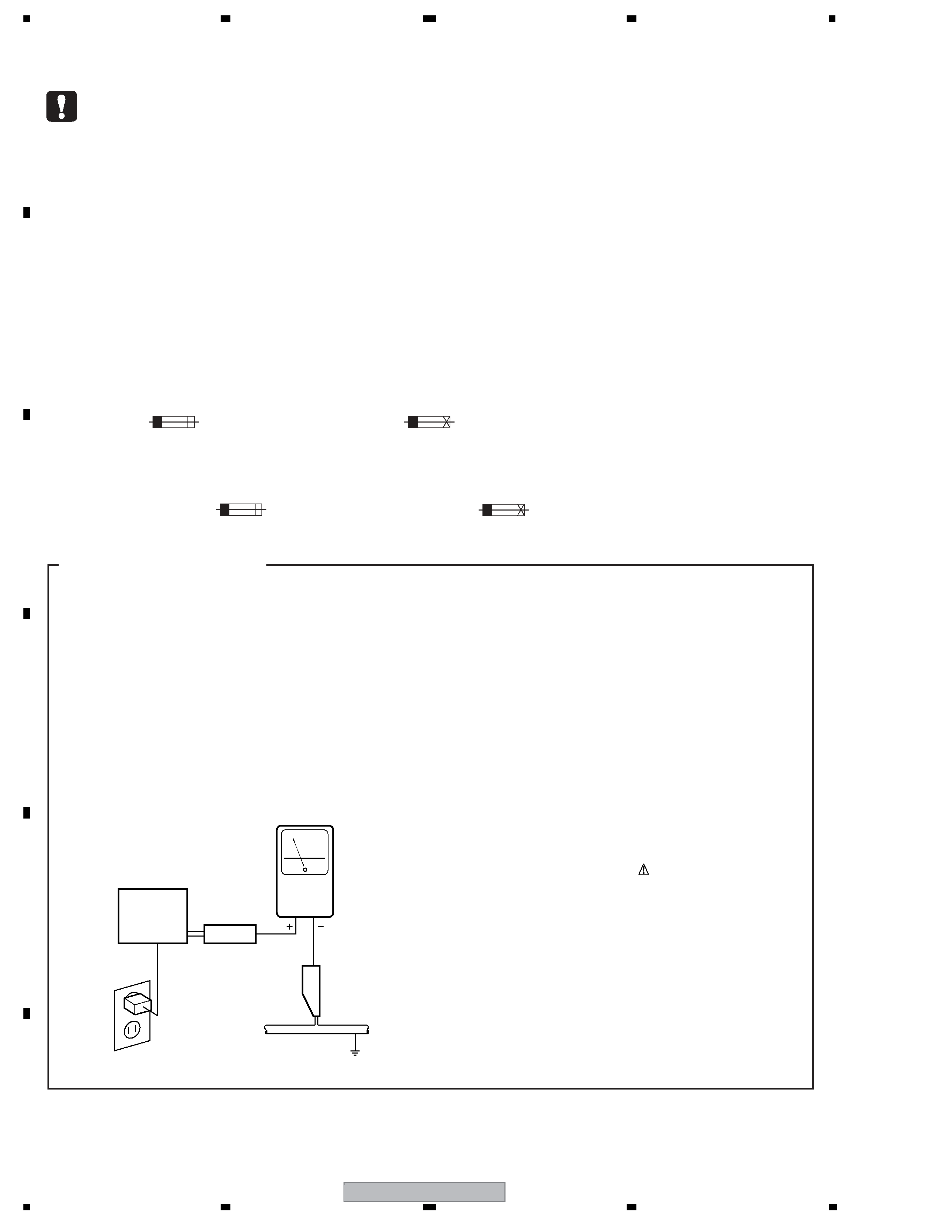
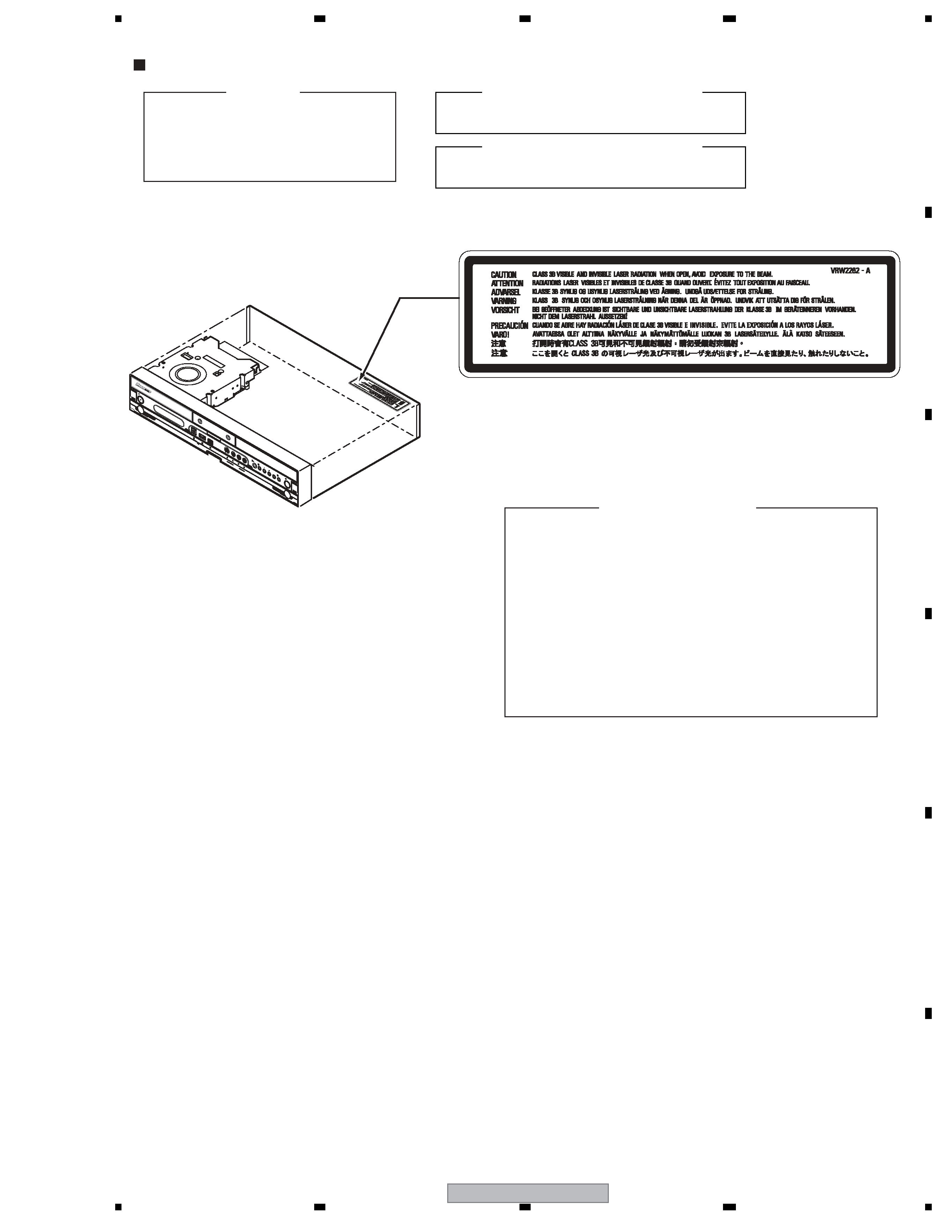
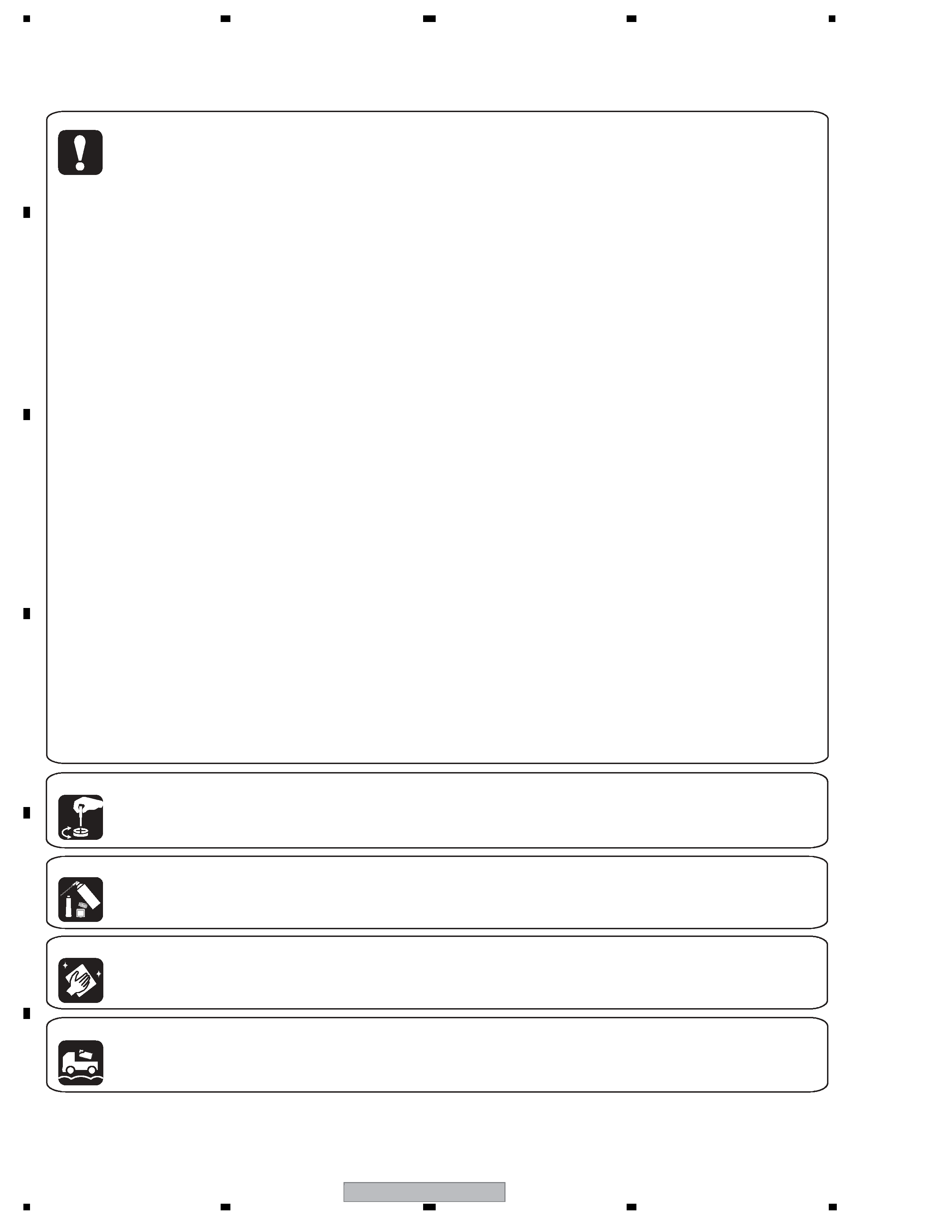
SAFETY INFORMATION......................................................................................................................................2
1. SPECIFICATIONS .............................................................................................................................................6
2. EXPLODED VIEWS AND PARTS LIST.............................................................................................................8
2.1 PACKING ....................................................................................................................................................8
2.2 EXTERIOR SECTION ..............................................................................................................................10
2.3 FRONT PANEL SECTION ........................................................................................................................12
3. BLOCK DIAGRAM AND SCHEMATIC DIAGRAM ..........................................................................................14
3.1 BLOCK DIAGRAM ....................................................................................................................................14
3.1.1 OVERALL BLOCK DIAGRAM ............................................................................................................14
3.1.2 AUDIO BLOCK DIAGRAM..................................................................................................................16
3.1.3 POWER BLOCK .................................................................................................................................17
3.2 OVERALL WIRING DIAGRAM .................................................................................................................18
3.3 TUJB ASSY (1/3) ......................................................................................................................................20
3.4 TUJB ASSY (2/3) ......................................................................................................................................22
3.5 TUJB ASSY(3/3) .......................................................................................................................................24
3.6 FJKB, FLKY and KEYB ASSYS ...............................................................................................................26
3.7 MAIN ASSY(1/4).......................................................................................................................................28
3.8 MAIN ASSY(2/4).......................................................................................................................................30
3.9 MAIN ASSY(3/4).......................................................................................................................................32
3.10 MAIN ASSY(4/4).....................................................................................................................................34
3.11 USBB ASSY (Except DVR-540H-S) .......................................................................................................36
3.12 ATAB ASSY.............................................................................................................................................37
3.13 POWER SUPPLY UNIT ..........................................................................................................................38
3.14 WAVE FORMS........................................................................................................................................40
4. PCB CONNECTION DIAGRAM ......................................................................................................................43
4.1 TUJB ASSY ..............................................................................................................................................44
4.2 FJKB, FLKY and KEYB ASSYS ...............................................................................................................48
4.3 MAIN ASSY ..............................................................................................................................................50
4.4 USBB ASSY (Except DVR-540H-S) .........................................................................................................54
4.5 ATAB ASSY...............................................................................................................................................56
4.6 POWER SUPPLY UNIT ............................................................................................................................58
5. PCB PARTS LIST ............................................................................................................................................60
6. ADJUSTMENT ................................................................................................................................................65
7. GENERAL INFORMATION .............................................................................................................................67
7.1 DIAGNOSIS ..............................................................................................................................................67
7.1.1 MODEL SETTING ..............................................................................................................................69
7.1.2 CPRM ID NUMBER AND DATA SETTING .........................................................................................70
7.1.3 FIRMWARE DOWNLOADING METHOD ...........................................................................................74
7.1.4 VIDEO ADJUSTMENT FOR SPECIFIC AREA...................................................................................77
7.1.5 SERVICE MODE ................................................................................................................................81
7.1.6 AGING MODE ....................................................................................................................................93
7.1.7 HDD CHECK MODE...........................................................................................................................95
7.1.8 DIAGNOSIS OF THE MAIN ASSY ...................................................................................................101
7.1.9 NOTE ON REPLACEMENT OF THE SDRAM..................................................................................102
7.1.10 SETUP SEQUENCE.......................................................................................................................103
7.1.11 DISASSEMBLY...............................................................................................................................104
7.2 IC ............................................................................................................................................................109
7.3 CAUTIONS ON HANDLING THE HDD...................................................................................................118
7.4 DISC/CONTENT FORMAT .....................................................................................................................120
8. PANEL FACILITIES .......................................................................................................................................123

Reviews

There are no reviews of this manual yet.