PIONEER CORPORATION
4-1, Meguro 1-Chome, Meguro-ku, Tokyo 153-8654, Japan
PIONEER ELECTRONICS (USA) INC.
P.O.Box 1760, Long Beach, CA 90801-1760 U.S.A.
PIONEER EUROPE NV
Haven 1087 Keetberglaan 1, 9120 Melsele, Belgium
PIONEER ELECTRONICS ASIACENTRE PTE.LTD. 253 Alexandra Road, #04-01, Singapore 159936
C PIONEER CORPORATION 2001
K-ZZS. SEPT. 2001 Printed in Japan
ORDER NO.
CRT2753
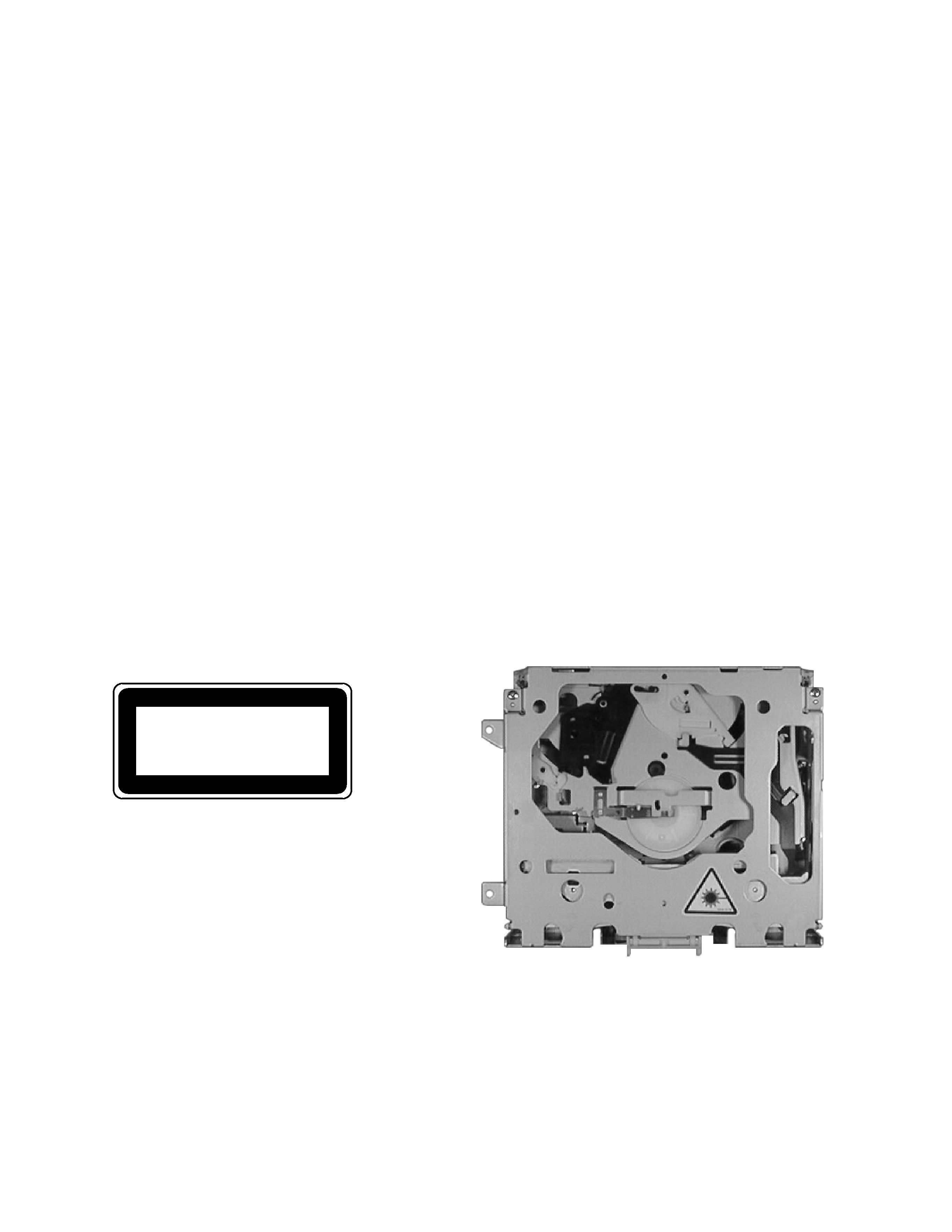
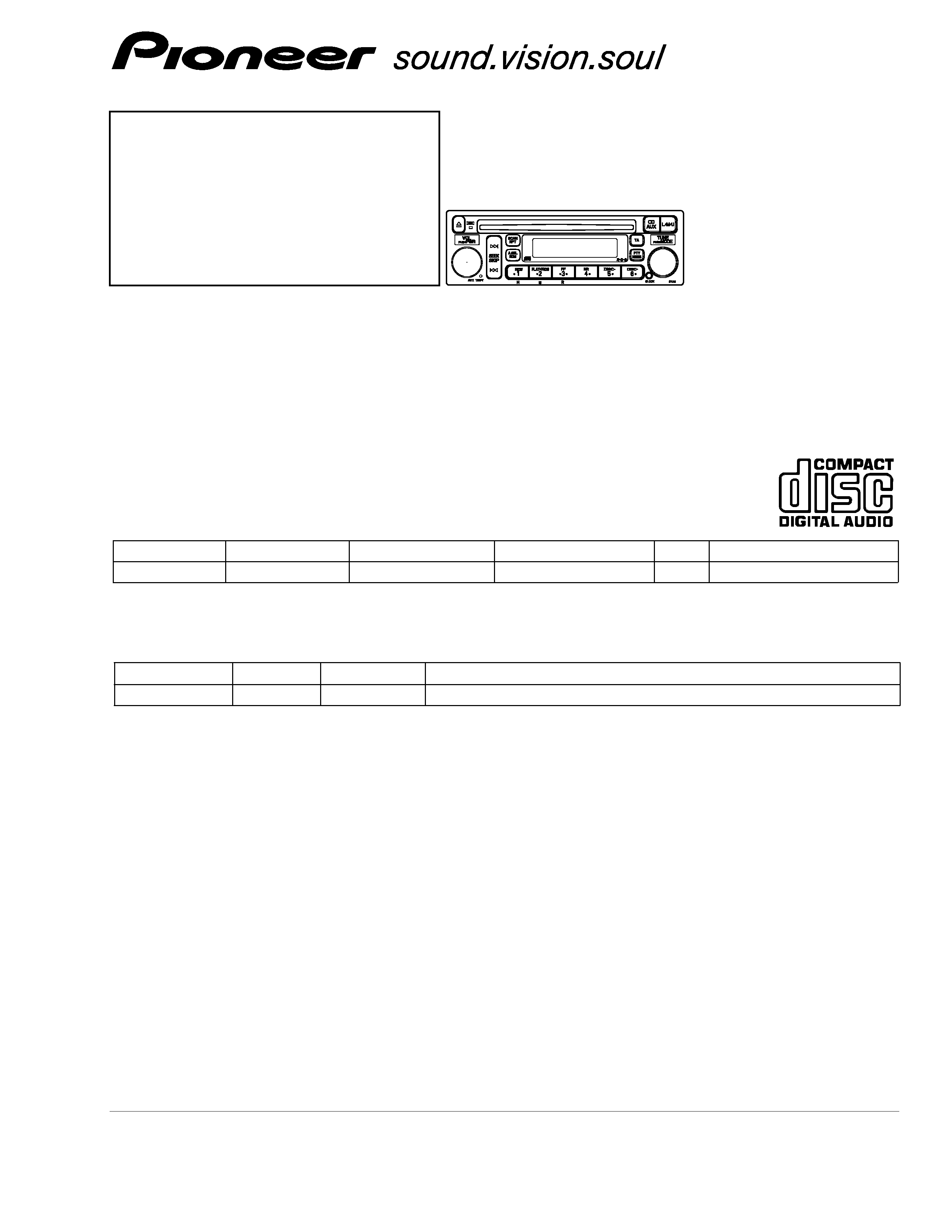
MULTI-CD CONTROL CD PLAYER WITH RDS TUNER
DEH-M7317ZH
EW
Service
Manual
HONDA
VEHICLE
DESTINATION
PRODUCED AFTER
HONDA PART No.
ID No.
PIONEER MODEL No.
S2000
EUROPE
August 2001
39101-S2A-G210-M1
3YA1
DEH-M7317ZH/EW
- This service manual should be used together with the following manual(s):
Model No.
Order No.
Mech. Module Remarks
CX-958
CRT2423
S8.1
CD Mech. Module:Circuit Description, Mech.Description, Disassembly
CONTENTS
1. SAFETY INFORMATION............................................2
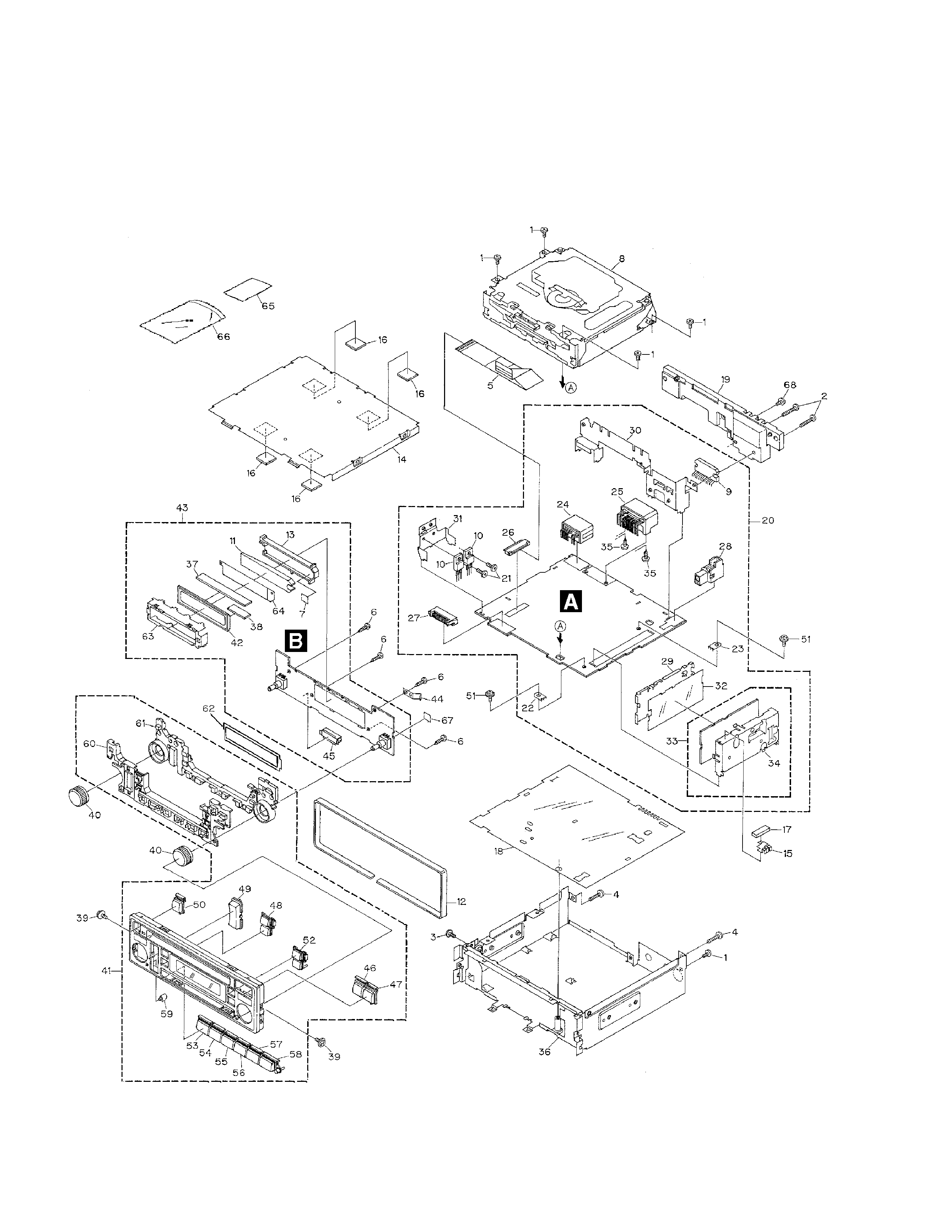
2. EXPLODED VIEWS AND PARTS LIST ......................4
3. BLOCK DIAGRAM AND SCHEMATIC DIAGRAM ....8
4. PCB CONNECTION DIAGRAM................................22
5. ELECTRICAL PARTS LIST........................................30
6. ADJUSTMENT .........................................................35
7. GENERAL INFORMATION.......................................41
7.1 DIAGNOSIS .......................................................41
7.1.1 DISASSEMBLY .........................................41
7.1.2 CONNECTOR FUNCTION DESCRIPTION ......46
7.2 PARTS ................................................................47
7.2.1 IC ...............................................................47
7.2.2 DISPLAY ...................................................51
7.3 OPERATIONAL FLOW CHART ..........................52
8. OPERATIONS AND SPECIFICATIONS ....................53