XV-DV350
5
56
78
56
7
8
C
D
F
A
B
E
1. SPECIFICATIONS
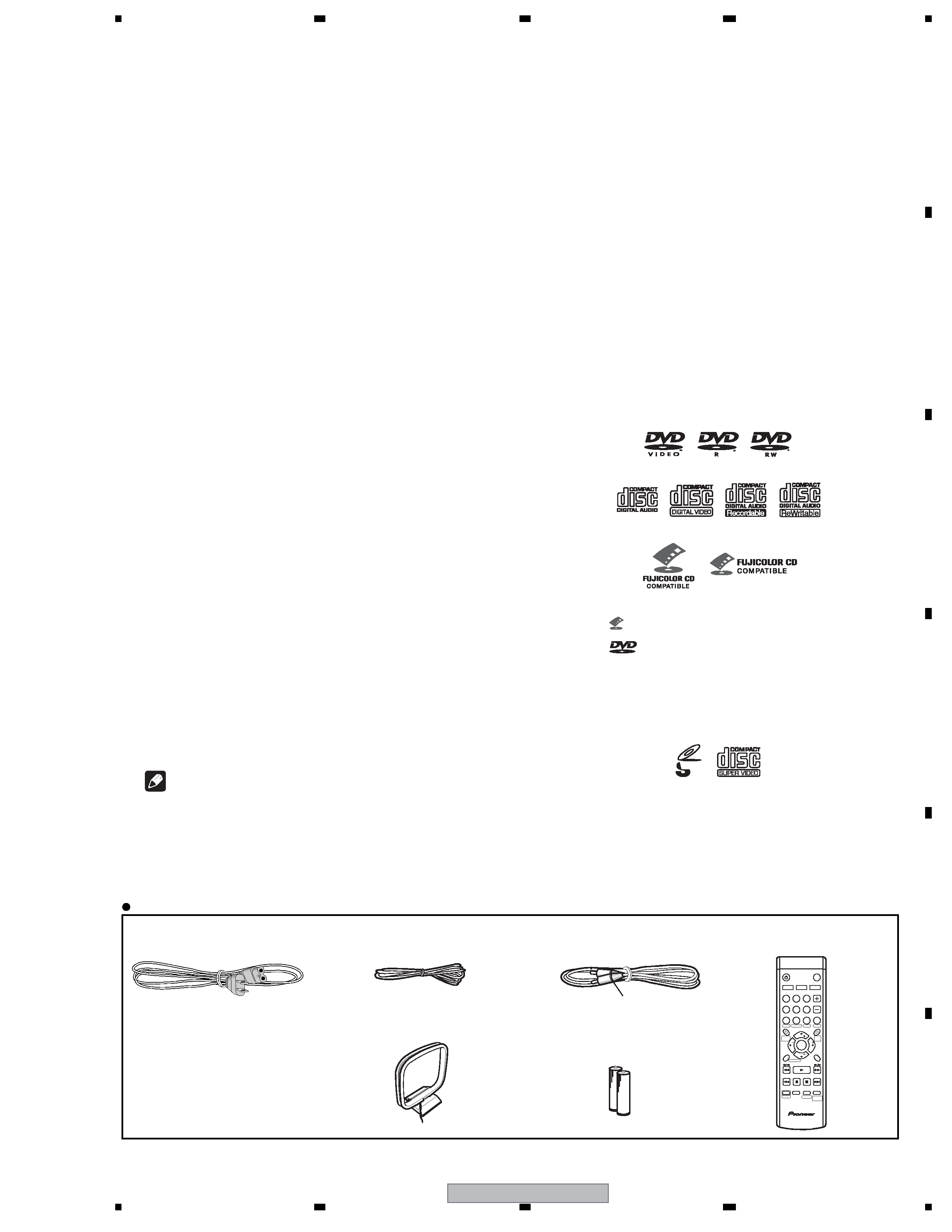
Accessories
· Power cord (ADG7021)
· FM Antenna (ADH7030)
· AM Loop Antenna
(ATB7013)
· Video Cable
(L = 1.5m) (XDE3046)
· Remote Control
(AXD7407)
· Dry Cell Batteries
Yellow
Note · Specifications and design subject to
possible modification without notice, due
to improvements.
Manufactured under license from Dolby
Laboratories."Dolby", "Pro Logic", and the
double-D symbol are trademarks of Dolby
Laboratories.
"DTS" and "DTS Digital Surround" are registered
trademarks of Digital Theater Systems, Inc.
Super Video CD (Super VCD)
Disc/content format playback
compatibility
This player is compatible with a wide range of
disc types (media) and formats. Playable discs
will generally feature one of the following logos
on the disc and/or disc packaging. Note
however that some disc types, such as
recordable CD and DVD, may be in an
unplayable format.
See the Disc compatibility tablebelow for more
information.
·
is a trademark of Fuji Photo Film Co. Ltd.
·
is a trademark of DVD Format/Logo
Licensing Corporation
· Also compatible with KODAK Picture CD
This player supports the IECís Super VCD stan-
dard for superior picture quality, dual
soundtracks, and widescreen support.
DVD-Video DVD-R
DVD-RW
Video CD
Fujicolor CD
Audio CD
CD-R
CD-RW
VIDEO
CD
·
Amplifier section
Continuous Power Output (FTC):
Front, Center, Surround
. . . . . . . . . . . . . . . . . . . . .13 W per channel*
(200 Hz 20 kHz, 1.0 %**, 6
)
Subwoofer. . . . . . . . . . . . . . . . . . . . . . .13 W*
(45 Hz 200 Hz, 1.0 %**, 6
)
·
Disc section
Digital audio
characteristics . . . . . . . . DVD fs: 96 kHz, 24-bit
Type . . . . . DVD system, Video CD/Super VCD
system and Compact Disc digital audio system
Frequency
response . . . 4 Hz to 44 kHz (96kHz sampling) /
4 Hz to 22 kHz (48kHz sampling)
Wow and Flutter . . . . . . . Limit of measurement
(
±0.001 % W.PEAK) or less (JEITA)
·
FM tuner section
Frequency range. . . . . . . 87.5 MHz to 108 MHz
Antenna. . . . . . . . . . . . . . . . . 75
, unbalanced
·
AM tuner section
Frequency range:
With 9kHz step . . . . . . 531 kHz to 1,602 kHz
With 10kHz step . . . . . 530 kHz to 1,700 kHz
Antenna. . . . . . . . . . . . . . . . . . . . Loop antenna
·
Miscellaneous
Power requirements. . . . . . . . AC 120 V, 60 Hz
Power consumption. . . . . . . . . . . . . . . . . . 45 W
Power consumption in standby. . . . . . . 0.25 W
Dimensions. . . 420 (W) x 60 (H) x 331.5 (D) mm
(169/16 (W) x 23/8 (H) x 13 (D) in.)
Weight . . . . . . . . . . . . . . . . 3.1 kg / 6 lbs. 13 oz.
·
Accessories (DVD/CD receiver)
Remote control . . . . . . . . . . . . . . . . . . . . . . . . 1
AA/R6 dry cell batteries . . . . . . . . . . . . . . . . . 2
Video cable (yellow plugs) . . . . . . . . . . . . . . . 1
AM loop antenna . . . . . . . . . . . . . . . . . . . . . . 1
FM antenna . . . . . . . . . . . . . . . . . . . . . . . . . . 1
Power cord. . . . . . . . . . . . . . . . . . . . . . . . . . . 1
Setup Guide . . . . . . . . . . . . . . . . . . . . . . . . . . 1
Warranty card . . . . . . . . . . . . . . . . . . . . . . . . . 1
Operating instructions
AUDIO SUBTITLE ANGLE
ZOOM
STANDBY/ON
MUTE
DVD/CD
FM/AM
TUNER
LINE
SYSTEM
SETUP
HOME
MENU
DVD
MENU
TOP
MENU
RETURN
TEST TONE
SOUND
MODE
SHIFT
CLEAR
SLEEP DISPLAY
VOLUME
12
3
45
6
78
9
0
TUNE
TUNE
ST
ST
ENTER
SURROUND FRONT
SURROUND
RMS Power Output :
Front, Center, Surround. . . 60 W per channel
(1 kHz, 10 % T.H.D., 4
)
50 W per channel
(1 kHz, 10 % T.H.D., 6
)
Subwoofer. . .60 W (100 Hz, 10 % T.H.D., 4
)
50 W (100 Hz, 10 % T.H.D., 6
)
* Measured pursuant to the Federal Trade
Commission's Trade Regulation rule on Power
Output Claims for Amplifiers.
** Measured by audio spectrum analyzer.