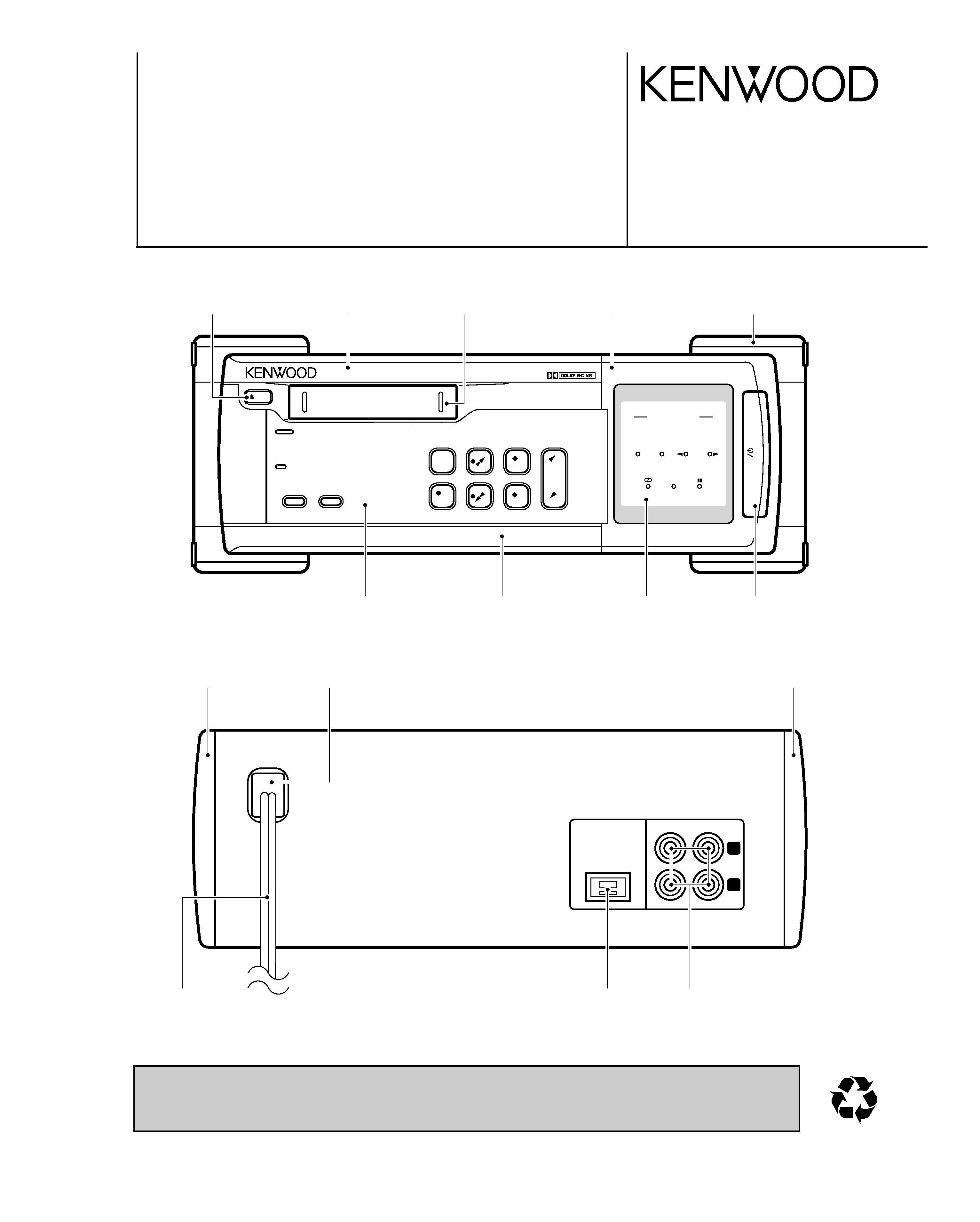
X-VH7
2
CONTENTS / ACCESSORIES
DISASSEMBLY FOR REPAIR
CONTENTS / ACCESSORIES .................................. 2
DISASSEMBLY FOR REPAIR....................................2
CIRCUIT DESCRIPTION ............................................3
ADJUSTMENT ............................................................6
PC BOARD ................................................................ 7
SCHEMATIC DIAGRAM ............................................ 9
EXPLODED VIEW ....................................................12
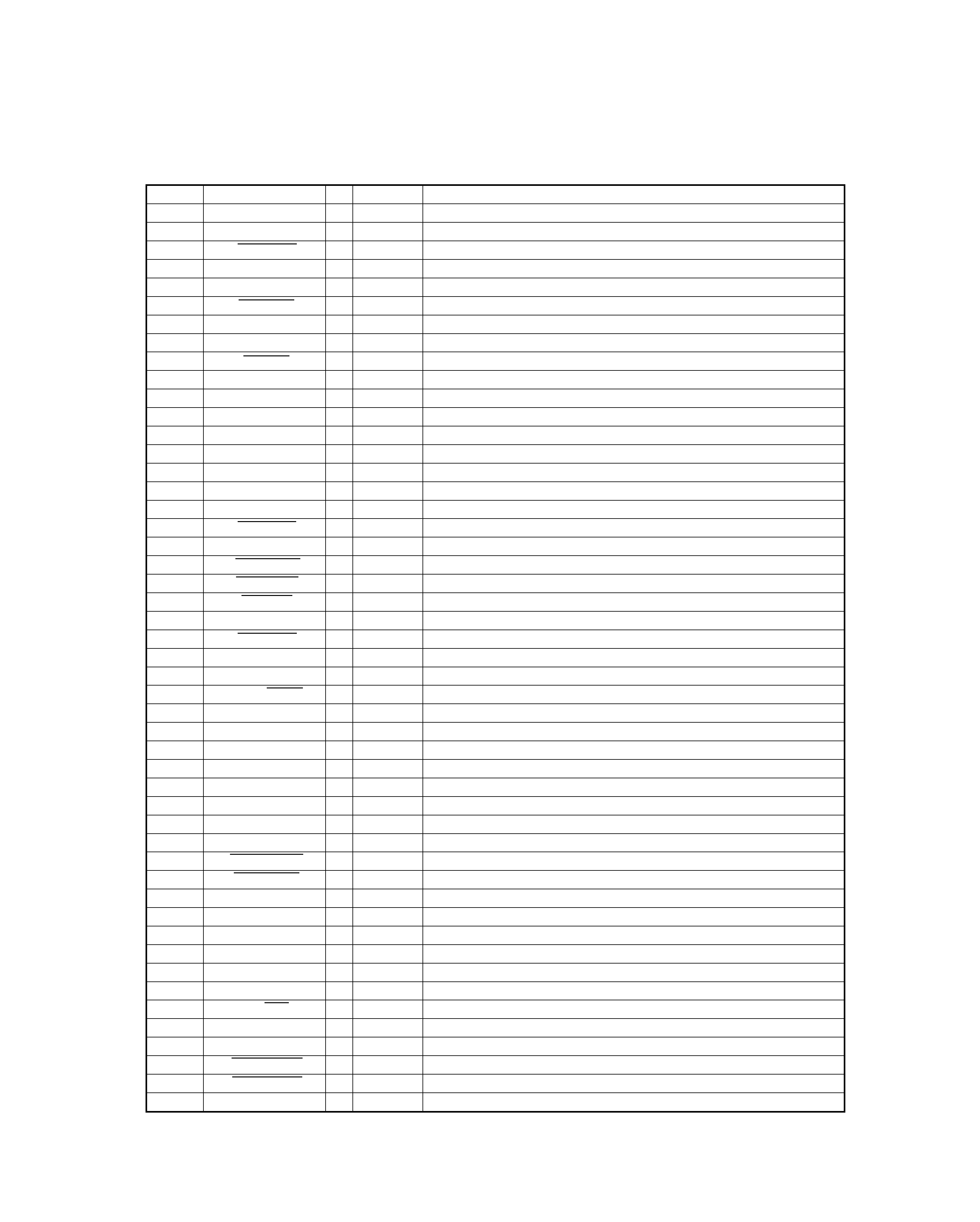
PARTS LIST..............................................................13
SPECIFICATIONS ......................................Back cover
Contents
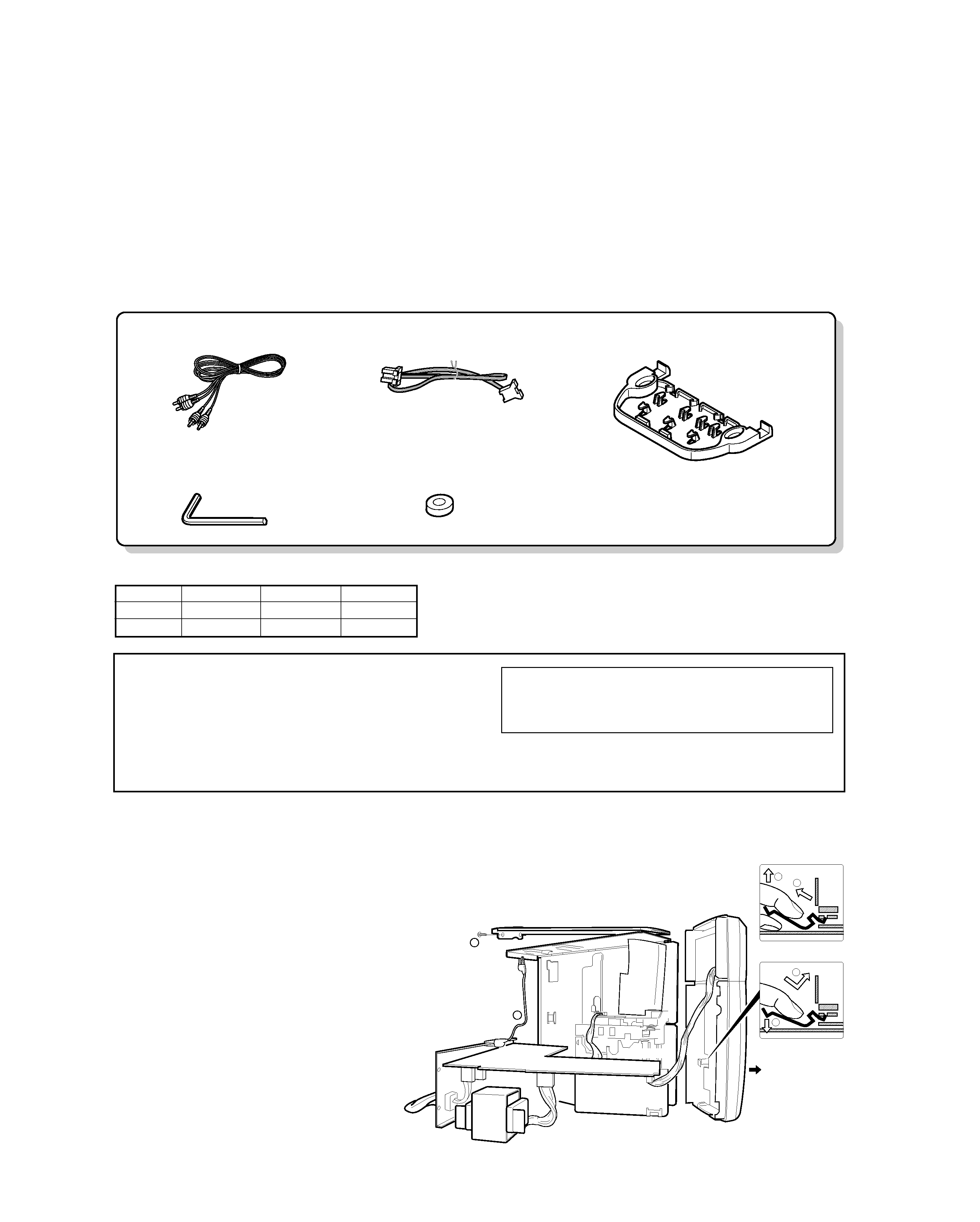
Accessories
Audio cord (2)
(E30-0615-05)
Front feet replacement tool (1)
(Allen wrench)
(W01-0084-05)
Replancement front feet (2)
(J02-0130-05)
System control cord (1)
(E30-2628-05)
Spacer for stacked installation (1)
(J19-5996-02)
REMOVE EARTH METAL
3
4
1
FRONT
X28 (A/4)
x2
2
DECK MECHA
ASSEMBLY EARTH METAL
6
5
ELECTRIC CHECK
1) Remove insulator a'ssy, then remove some
screw of L,R side board(
1). Next remove the
top and the bottom boards, then remove the
power transformer and the rear panel assem-
bling PCB.
2) Connect GND between PCB and the deck
mechanism with a alligator clip lead weir (
2).
REMOVE EARTH METAL
Support the earth metal by your finger to
keep the shape, then pull up (
3) and remove
(
4) the earth metal .
ASSEMBLE EARTH METAL
Insert the tip of the earth metal (
5), then sup-
port the earth metal by your finger, push
down it (
6).
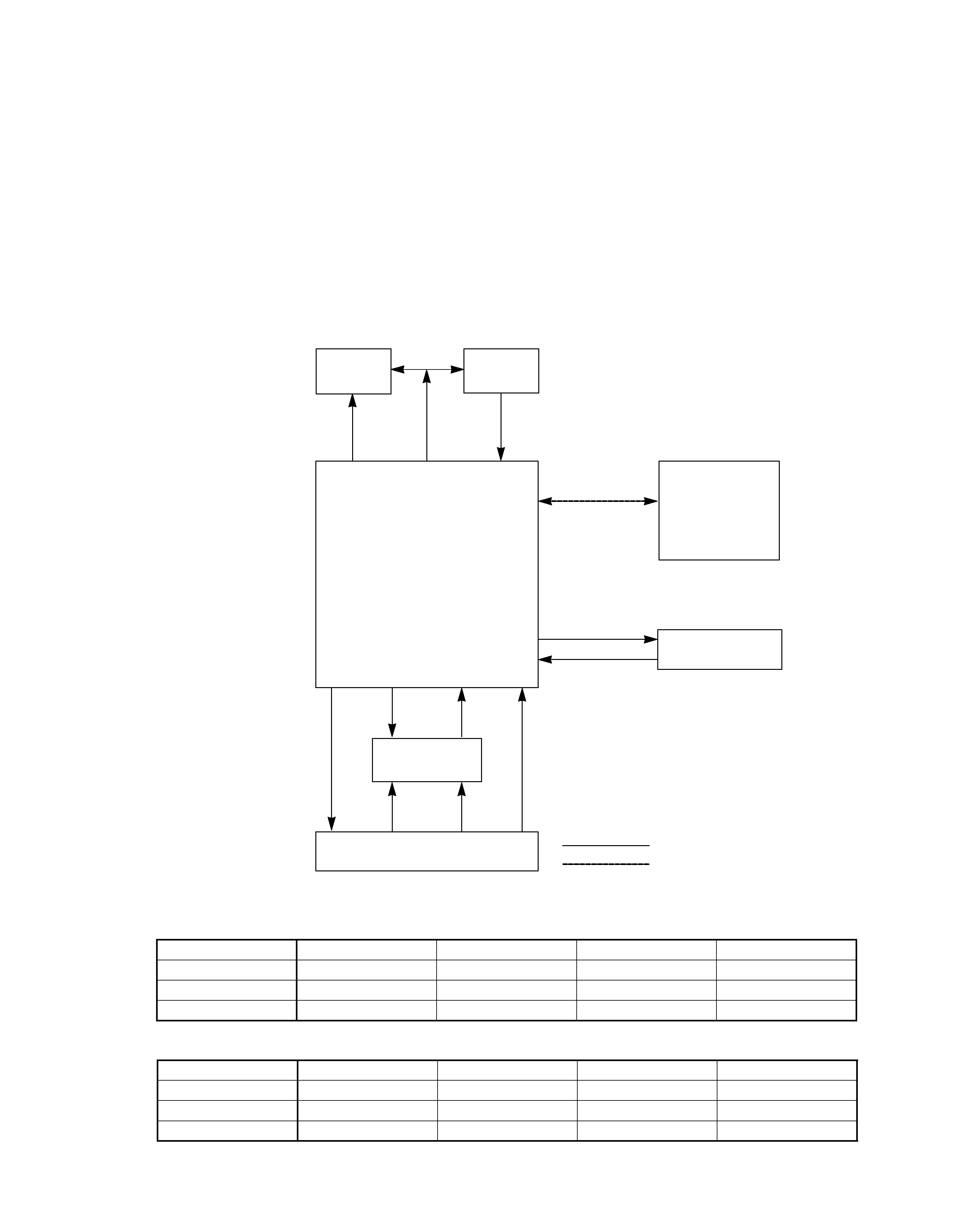
System configurations
SYSTEM
RECEIVER
CASSETTE SPEAKER
VH-600
RD-VH7
-
LS-VH7
VH-700
RD-VH7
X-VH7
LS-VH7
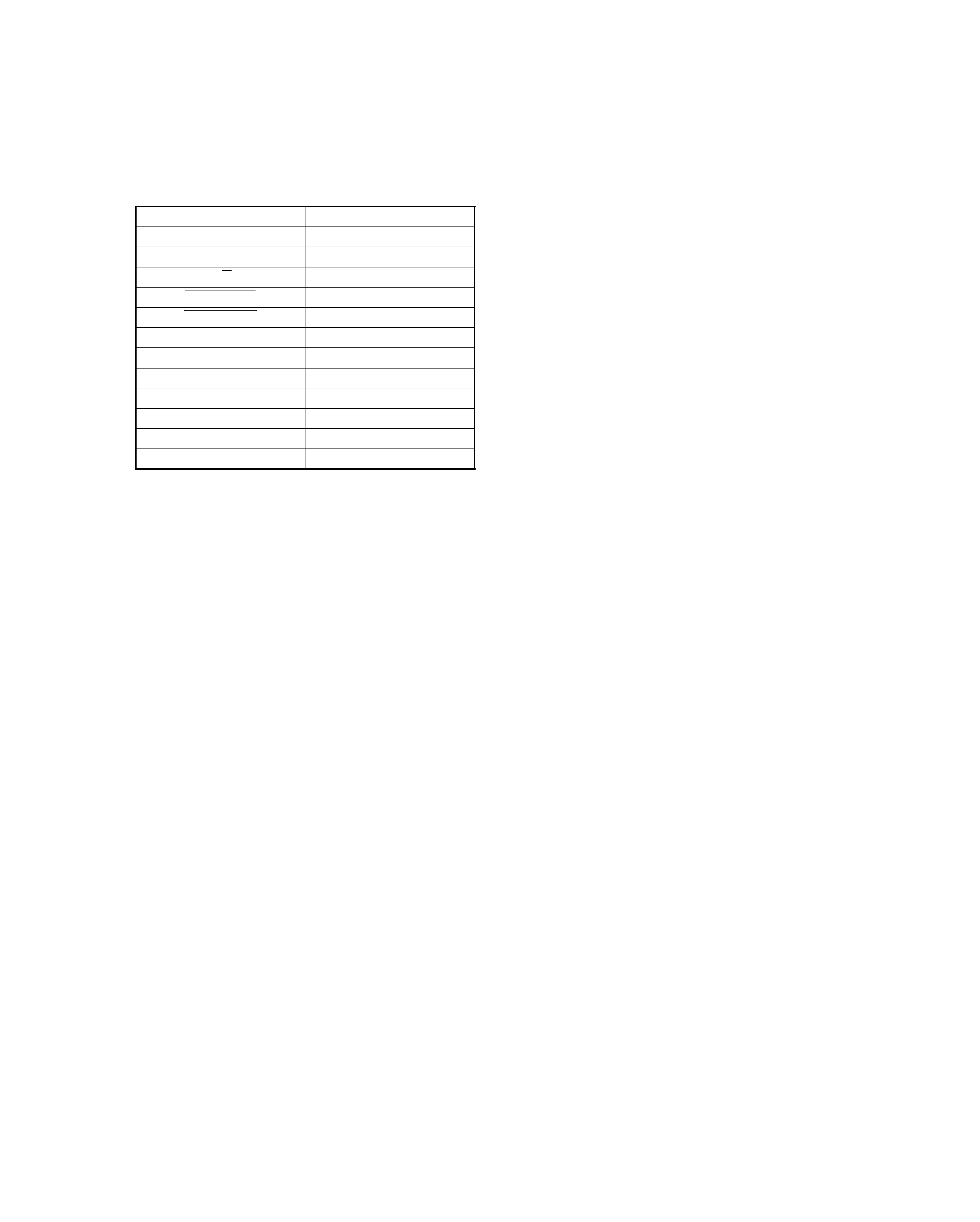
Operation to reset
The microcomputer may fall into malfunction (impossi-
bility to operate, erroneous display,
etc.) when the
power cord is unplugged while power is ON or due to
an external factor. In this case, execute the following
procedure to reset the microcomputer and return it to
normal condition.
¶ Please note that resetting the microcomputer clears the contents
stored in it returns it to condition when it left the factory.
Unplug the power cord from the AC outlet and, while
holding the "
0
0eject" key depressed, plug the power
cord again.
¶ If a tape is loaded in the deck, it will be ejected now.
X-VH7(K) COVER1,1P( 99.11.1 11:14 AM y[W 3