TK-3202/3206
3
REALIGNMENT
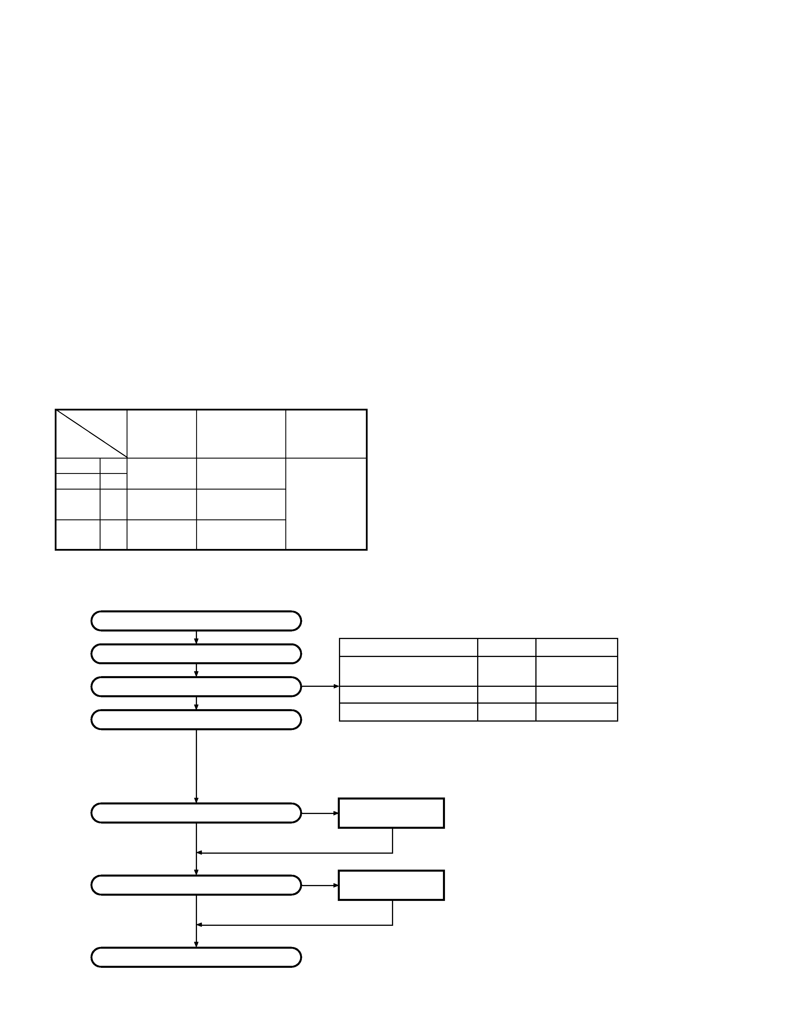
1. Modes
Mode
Function
User mode
For normal use.
PC mode
Used for communication between the
radio and PC (IBM compatible).
Data programming
Used to read and write frequency data
mode
and other features to and from the radio.
PC test mode
Used to check the radio using the PC.
This feature is included in the KPG-
87D.
Clone mode
Used to transfer programming data
from one radio to another.
User mode
PC mode
PC test mode
Data programming
mode
PC tuning mode
REALIGNMENT
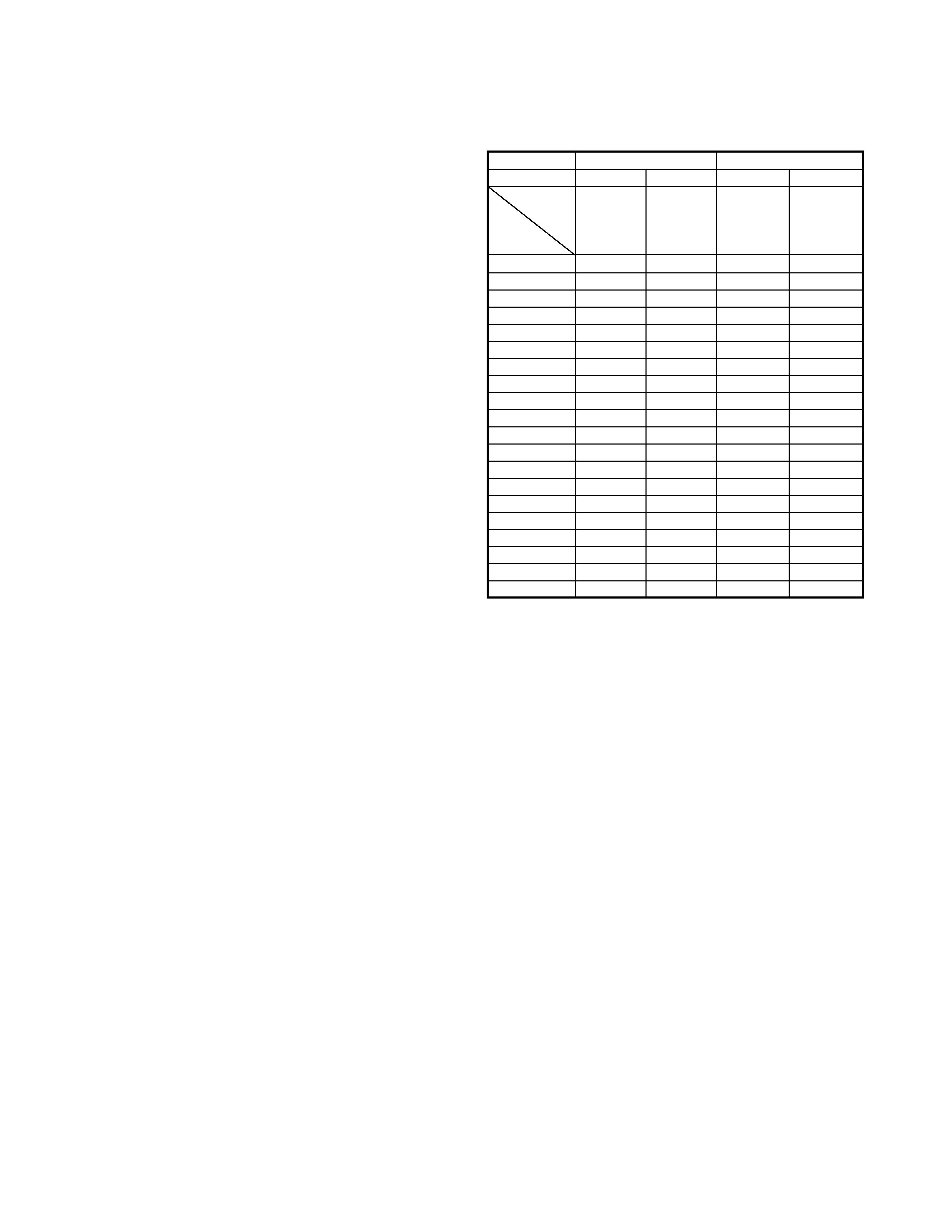
3.PC Mode
3-1. Preface
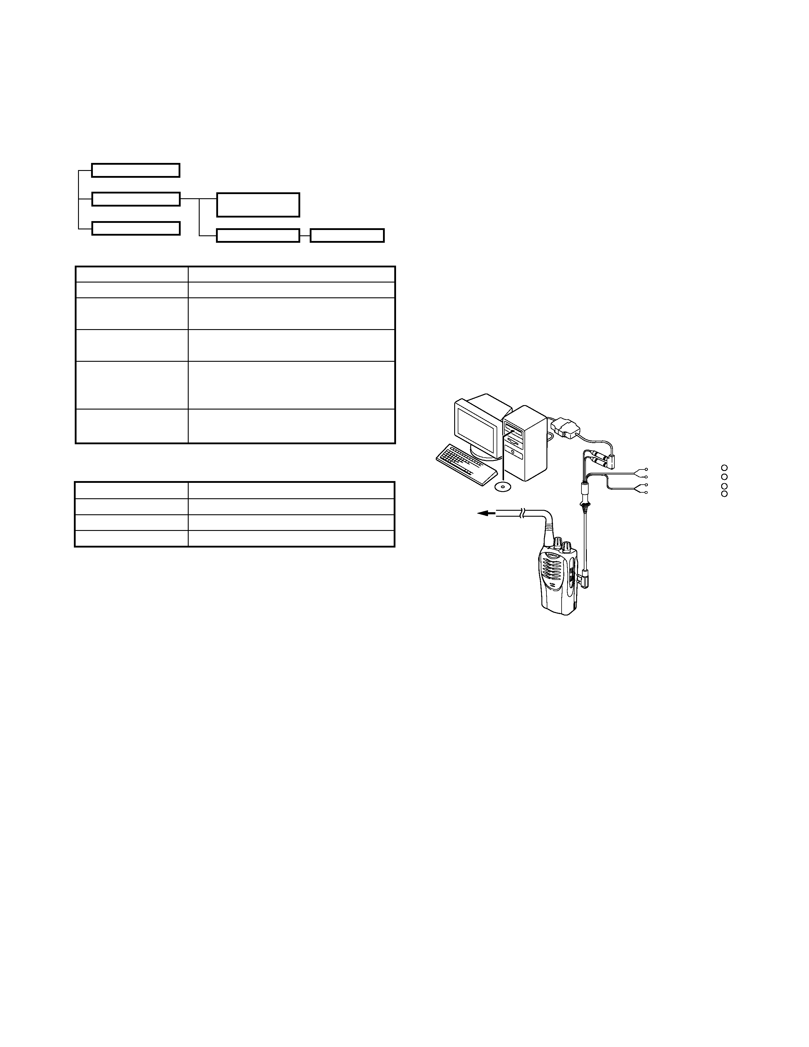
The TK-3202/3206 transceivers are programmed using a
personal computer, a programming interface (KPG-22) and
programming software (KPG-87D).
The programming software can be used with an IBM PC
or compatible. Figure 1 shows the setup of an IBM PC for
programming.
3-2. Connection procedure
1. Connect the TK-3202/3206 to the personal computer with
the interface cable.
2. When the POWER is switched on, user mode can be
entered immediately. When the PC sends a command,
the radio enters PC mode.
When data is transmitting from the transceiver, the red
LED lights.
When data is received by the transceiver, the green LED
lights.
Notes:
·
The data stored in the personal computer must match the
model type when it is written into the EEPROM.
·
Change the TK-3202/3206 to PC mode, then attach the
interface cable.
3-3. KPG-22 description
(PC programming interface cable: Option)
The KPG-22 is required to interface the TK-3202/3206 with
the computer. It has a circuit in its D-subconnector (25-pin)
case that converts the RS-232C logic level to the TTL level.
The KPG-22 connects the SP/MIC connector of the TK-3202/
3206 to the computer's RS-232C serial port.
3-4. Programming software description
KPG-87D is the programming software for TK-3202/3206
supplied on a CD-ROM. This software runs under Windows
98, ME, Windows 2000 or XP on an IBM-PC or compatible
machine.
The data can be input to or read from TK-3202/3206 and
edited on the screen. The programmed or edited data can be
printed out. It is also possible to tune the transceiver.
Tuning cable
(E30-3216-05)
RF Power meter
or SSG
Gray
+
Gray/Black
1.5D-XV Lead wire
+
1.5D-XV Shield wire
}
}
SP
MIC
KPG-22
KPG-87D
IBM-PC
Fig. 1
Clone mode
2. How to Enter Each Mode
Mode
Operation
User mode
Power ON
PC mode
Received commands from PC
Clone mode
[PTT]+[Side2]+Power ON (Two seconds)
4. Clone Mode
4-1. Outline
"Clone Mode" copies the transceiver data to another
transceiver.
The dealer can copy the transceiver data to another
transceiver even without the use of a personal computer.
4-2. Example
The transceiver can copy the programming data to one or
more transceivers via RF communication.
The clone master and clone slave/s must be in Clone mode.
4-3. Operation
1. To switch the clone slave/s to Clone mode, press and hold
the [PTT] and [side2] keys while turning the transceiver
power ON.
2. Wait for 2 seconds. The LED will light orange and the
transceiver will announce "Clone".
3. Select a channel table number using Side1(increment
channel table) and Side2(decrement channnel table) keys.