KENWOOD LZH-70W Owner's Manual

Cover page of KENWOOD LZH-70W Owner's Manual

Owner's Manual for KENWOOD LZH-70W, downloadable as a PDF file.

Manual details

  • Immediate download after payment.
  • Delivered as a PDF file.
  • The manual has 44 pages
  • File size: 4.17 MB
  • Available language versions: Portuguese, French, English, Spanish, Dutch, German, Italian
  • Different language versions may vary sligthly in file size and page count.

We guarantee that...

  • our manuals are complete,
  • our manuals are checked with antivirus,
  • We'll issue refund if the manual is damaged, incomplete or unreadable (our refund policy)

Sample pages

Thumbnail of page 1Thumbnail of page 2Thumbnail of page 3Thumbnail of page 4
Thumbnail of page 5Thumbnail of page 6Thumbnail of page 7Thumbnail of page 8
Thumbnail of page 9
background image
LZH-70W
OVERHEAD CONSOLE WITH 7" LCD SCREEN
7 page 2-7
INSTALLATION MANUAL
CONSOLE DE PLAFOND AVEC ÉCRAN ACL À DIAGONALE 7"
7 page 8-13
MANUEL D'INSTALLATION
OVERHEAD-KONSOLE MIT 7"-DIAGONAL-LCD-BILDSCHIRM
7 Seite 14-19
INSTALLATION-HANDBUCH
PLAFONDCONSOLE MET 7" DIAGONAAL LCD-SCHERM
7 blz 20-25
INSTALLATIE HANDLEIDING
CONSOLLE SOVRATESTA CON DISPLAY LCD DIAGONALE A 7 POLLICI
7 pagina 26-31
MANUALE DI INSTALLAZIONE
CONSOLA DE TECHO CON PANTALLA LCD DE 7"
7 página 32-37
MANUAL DE INSTALACIÓN
CONSOLA ELEVADA COM ECRÃ LCD DE 7" DE DIAGONAL
7 página 38-43
MANUAL DE INSTALAÇÃO
© 2004 KENWOOD
background image
Before you begin:
WARNING
· To minimise the risk of improper installation, Kenwood recommends that the installation of this
product be performed by an MECP-Certified professional installer. Improper installation may
cause damage to the vehicle or injury to the driver and occupants.
· Installation must be performed according to these installation instructions. Kenwood is not
responsible for damages or injuries resulting from installation not performed strictly in
accordance with the procedures described in these instructions.
· Proper installation of this product may require the use of mounting hardware not included with this
product.
· Use only new, unused and properly-sized fasteners to install this product. Do not use
previously-installed or worn fasteners.
· No modifications to the product is permitted.
· This product is designed to be used and viewed by rear-seat passengers only. The monitor screen
must not be visible to the driver. Viewing by the driver while operating the vehicle will create an
unsafe condition.
· Kenwood does not recommend connecting hanging wires or cables to auxiliary connectors while the
vehicle is in motion.
· This product must not obstruct the driver's rear view when installed or used.
· It is the responsibility of the purchaser and installer to comply with all applicable laws and
regulations governing the installation and use of this product.
· Kenwood disclaims all liability for any property damage or personal injury that may result from
improper or unintended installation or use of this product.
CONGRATULATIONS!
Your LZH-70W console lets rear-seat passengers enjoy audio/video entertainment from its 7" TV screen and wired &
wireless headphone outputs. These instructions contain instructions for installing the LZH-70W safely in a vehicle.
For the latest information about this and other Kenwood products, visit the Kenwood Corporation Web site at:
www.kenwood.com
2
LZH-70W Installation Instructions
Eng-LZH-70WInstallManual_01.qxd
04.5.28
2:06 PM
Page 2
background image
Box contents
Unpack your LZH-70W carefully and make sure that everything listed here is present:
LZH-70W Installation Instructions
3
DOME
LIGHT
POWER
ATT
SW
1 x Hardware Package
1 x RC-70W Wireless
Remote Control
1 x LZH-70W
Overhead Console
1 x 46-cm A/V1 ­ A/V2 Input
Pigtail Connector
(part #Y662135-A)
1 x 46-cm A/V Output
Pigtail Connector
(part #Y662129-A)
1 x 5.5-m Main Power
Wiring Harness
(part #Y662133-A)
1 x 5-m A/V1 Input
Wiring Harness
(part #Y662136-A)
1 x 5-m A/V2 Input
Wiring Harness
(part #Y662161-A)
1 x 46-cm Power/Dome Light/
Mute Switch Pigtail Connector
(part #Y662131-A)
1 x 46-cm Wired Headphone
Output Connector
(part #Y662130-A)
1 x 61-cm Dome Light
Wiring Harness
(part #Y662132-A)
1 x 5.5-m Parental
Interrupt/Mute Switch
(part #Y662134-A)
1 x 49.5-cm IR1 Infrared Emitter
(part #Y662137-A)
1 x 49.5-cm IR2 Infrared Emitter
(part #Y662162-A)
If anything is missing or damaged, or if your LZH-70W fails to operate, notify your dealer immediately. If your
LZH-70W was shipped to you directly, notify your shipper immediately. Kenwood recommends that you retain the original car-
ton and packing materials in case you need to ship your LZH-70W in the future.
Note: "IR1" on tag
Note: "IR2" on tag
Eng-LZH-70WInstallManual_01.qxd
04.5.28
2:06 PM
Page 3
background image
Installation procedure
Note: The following description is for a standard installa-
tion. It may have to be adapted to suit your vehicle. For
queries relating to installation procedures and/or mount-
ing hardware, please contact your dealer or a company
offering equivalent components. Kenwood recommends
having a qualified technician install the monitor.
1. Determine the mounting location for the console.
· The mounting location is differed depending on the
vehicle's type.
· Ensure that when opened, the monitor will not obstruct
the driver's rear view.
· Remove the vehicle's overhead console and dome lamp if
they interfere with the console.
2. Apply masking tape to the headliner and mark the
console's mounting location.
· Use the included template as a guide.
3. Using the included template as a guide, cut the wire
access hole in the headliner.
4. Once the access hole is cut in the headliner, use a mark-
ing pen to trace the outline of the hole on the inside of
the vehicle's roof.
5. Carefully remove the headliner.
· Before you begin make sure the headliner is not glued-in.
· Remove visors, consoles, handles, pillar covers, and
anything that attaches the headliner to the vehicle.
· Make sure not to crease the headliner.
6. Mark the console's location on the inside of the roof:
a) Align the access hole in the template with the one you out-
lined on the roof.
b) Tape the template to the roof, making sure that it is prop-
erly aligned with the vehicle's centerline.
c) Use a marking pen to trace the outline of the template on
the inside of the roof.
7. Prepare bracket to install the console.
· Length:
Adjust to the length of crossmember
· Wide:
190 mm
· Thickness: More than 9 mm
8. Fix the bracket to the console's location marked inside
of the roof.
· Make sure screws are the correct length to avoid
damaging the vehicle roof.
4
LZH-70W Installation Instructions
Step 2: Marking the mounting location on the headliner
Step 7: Preparing the bracket
Make a hole to install the cable
Step 8: Attaching the bracket to the crossmembers
Guide Marks on Roof
Mounting Screws
Mounting Screws
Eng-LZH-70WInstallManual_01.qxd
04.5.28
2:06 PM
Page 4
background image
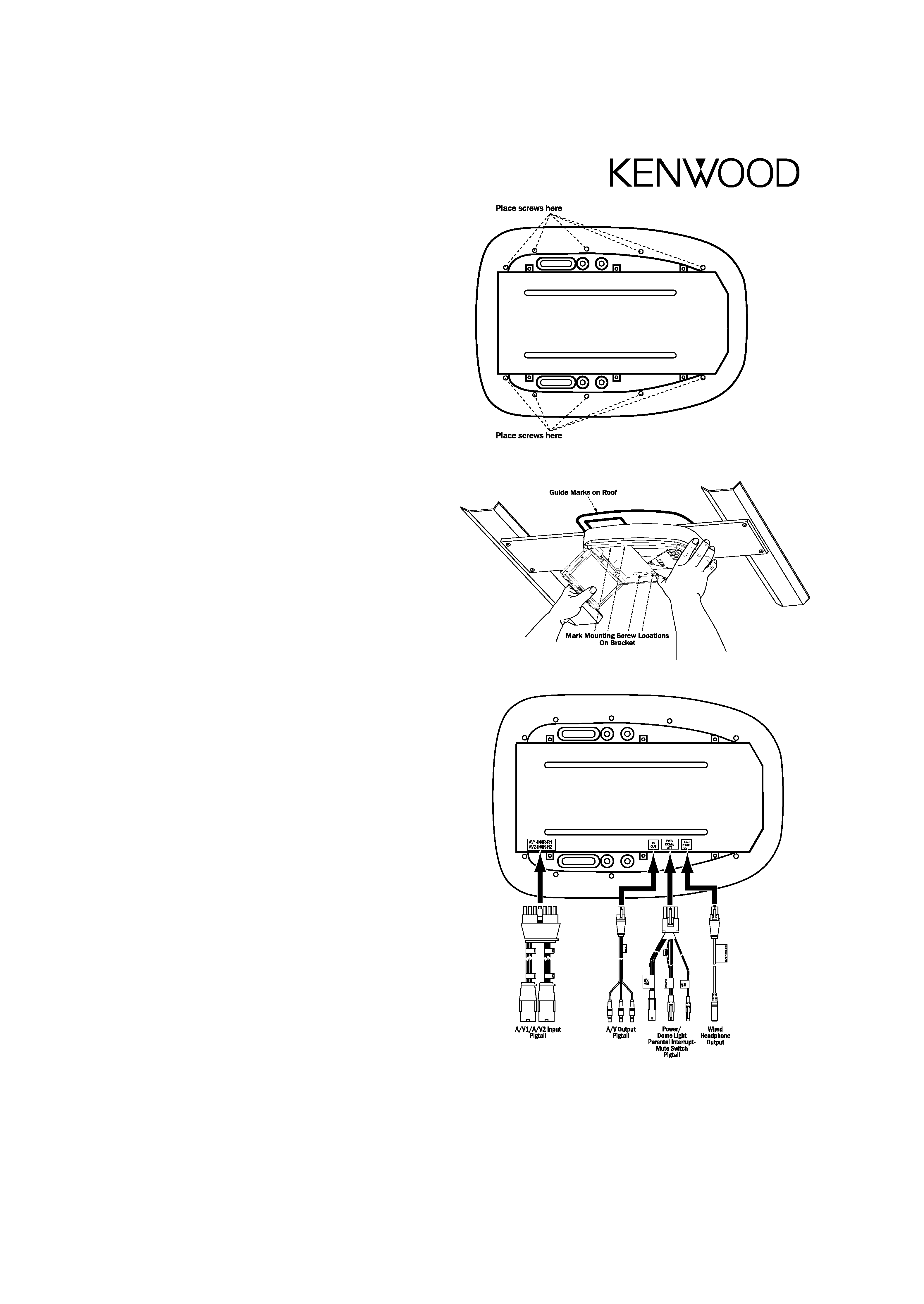
9. Attach the optional trim ring (model #SK-70TR) to the
console.
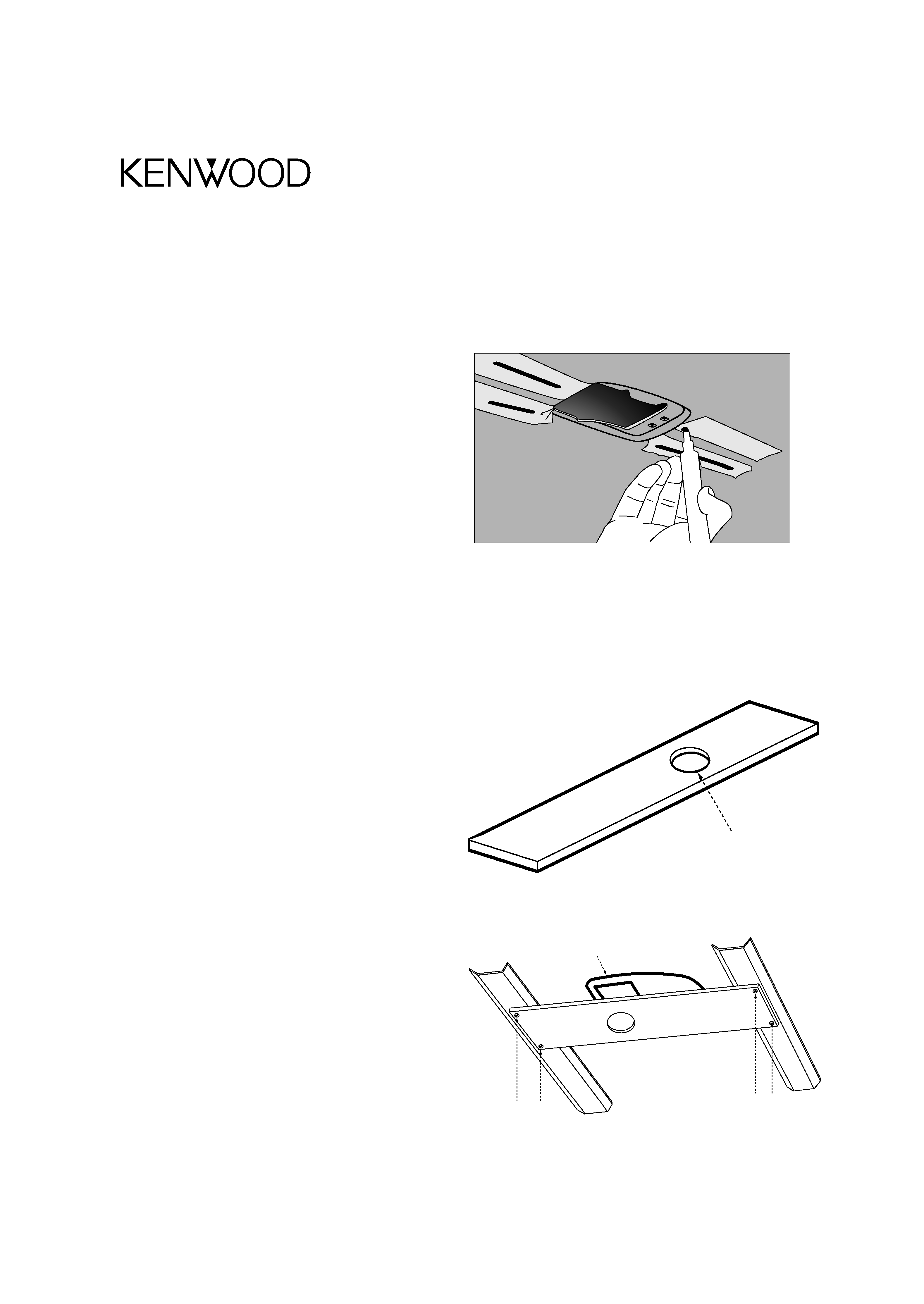
10. Using the marks on the roof as a guide, test-fit the con-
sole in its mounting location on the bracket assembly:
a) Open the LCD screen to expose the console's mounting
holes.
b) Using the marks on the roof as a guide, hold the
console against the mounting bracket in the mounting
location.
c) Mark the console's mounting screw hole locations on
the bracket and drill pilot holes.
d) Make sure screws are the correct length to avoid
damaging the vehicle roof.
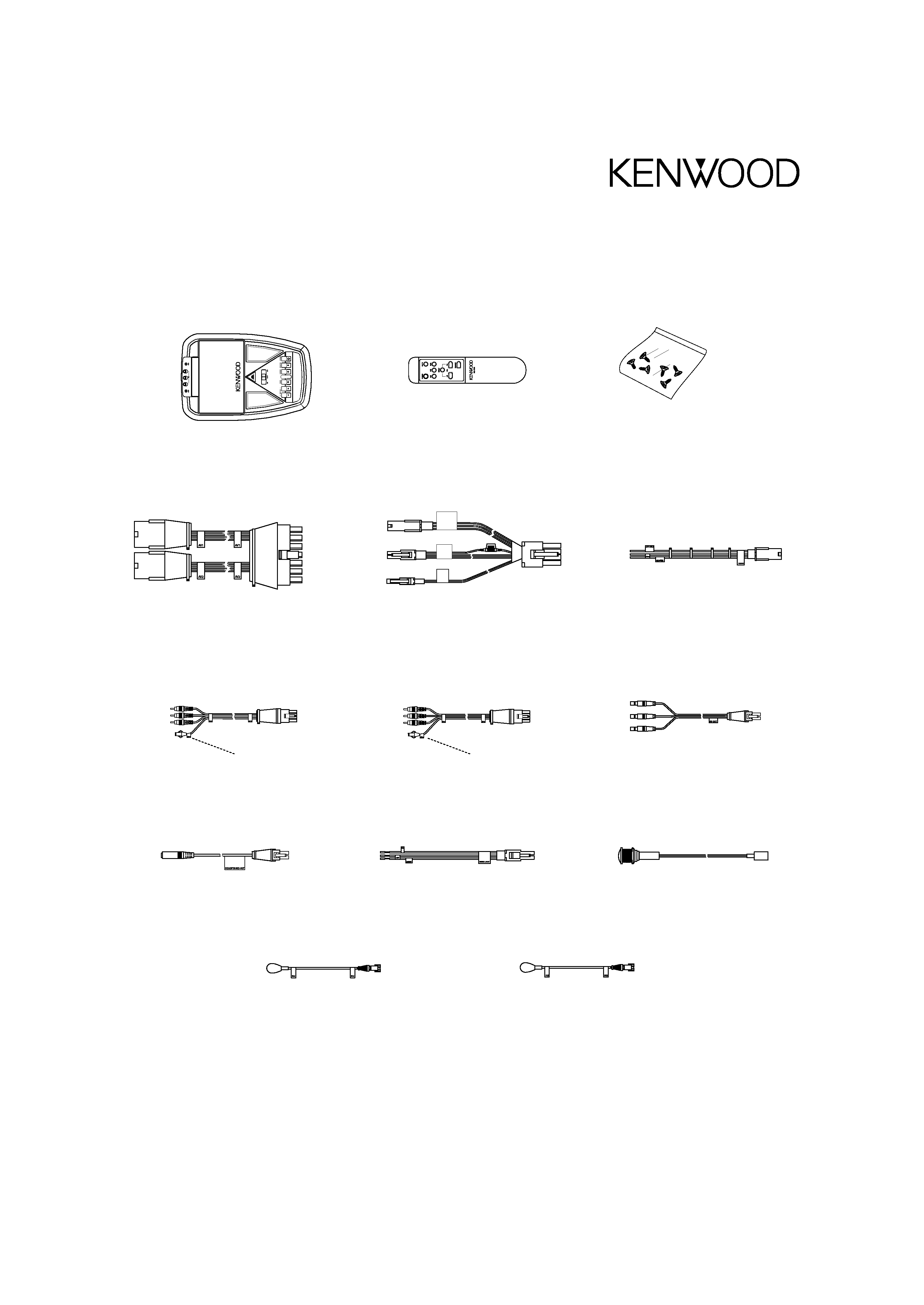
11. Wire all A/V input harnesses, A/V output harnesses,
the Parental Interrupt/Mute button, IR sensors and
power harness connections to the vehicle.
· Route their multipin connectors to the console
mounting location.
· Power harness wiring: Red = Switched +12 V Accessory;
Yellow = Constant +12 V; Black = Earth
· Mount the Parental Interrupt/Mute button in a location
easily accessible to the front-seat passengers.
12. Route all wiring harnesses through the vehicle and
through the access hole in the headliner.
· Route the wiring so there is no excess at the console
mounting location or above the headliner.
13. Re-attach the headliner.
· Start from the centre of the roof and work out towards the
sides, front, and rear.
· Ensure that all headliner attachment points are aligned.
· Re-install the visors and other hardware removed in
Step 5.
14. Make all pigtail harness connections to the console.
15. Connect the vehicle's dome lamp wires to the
LZH-70W Dome Light Wiring Harness:
With all of the vehicle doors closed and the lights off, place
the probes of a volt meter on the vehicle's dome light wires:
a) If the meter shows 0 V, the vehicle has a Positive
Switched system. Connect the LZH-70W's Dome Light
Wiring Harness in the following way:
· Blue wire -->
vehicle's switched dome light wire
· Orange wire --> fused constant 12 V source
· Green wire -->
a good earth point on the vehicle
LZH-70W Installation Instructions
5
Step 9: Attaching the trim ring to the console
Step 10: Test-fitting the console on the bracket
Step 14: Connecting the pigtails to the console
Eng-LZH-70WInstallManual_01.qxd
04.5.28
2:06 PM
Page 5

Reviews

There are no reviews of this manual yet.