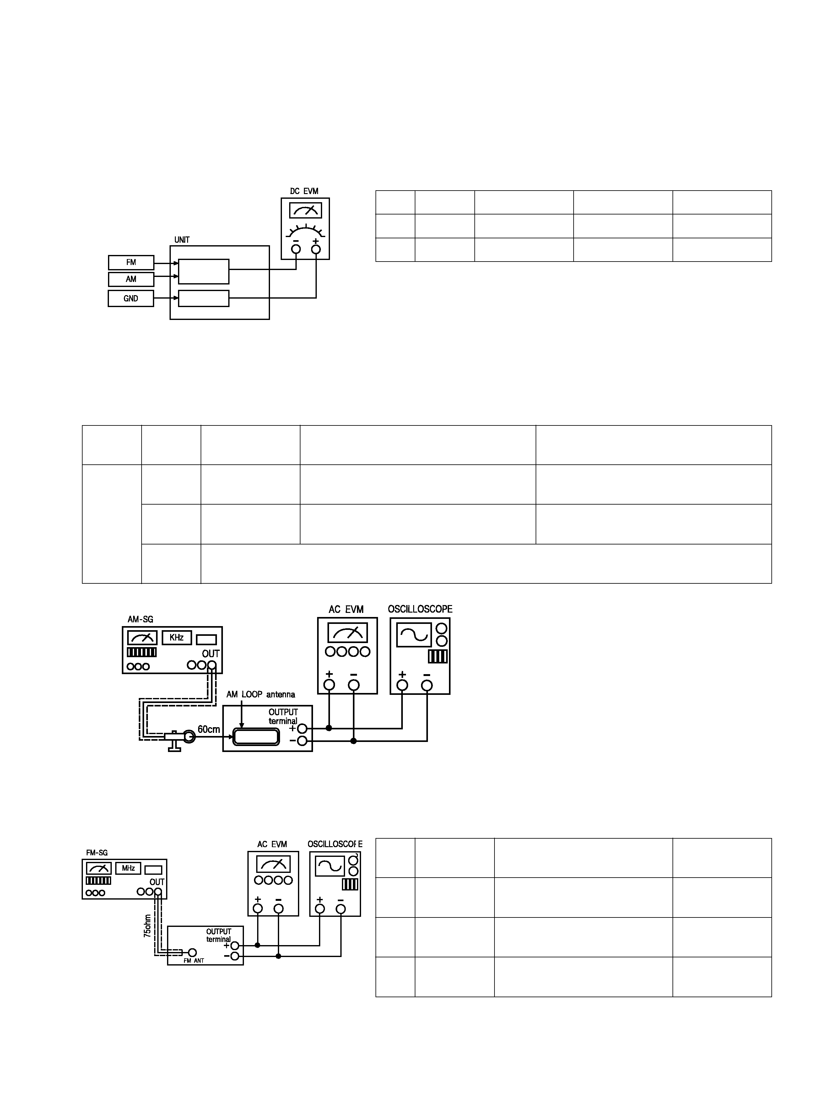
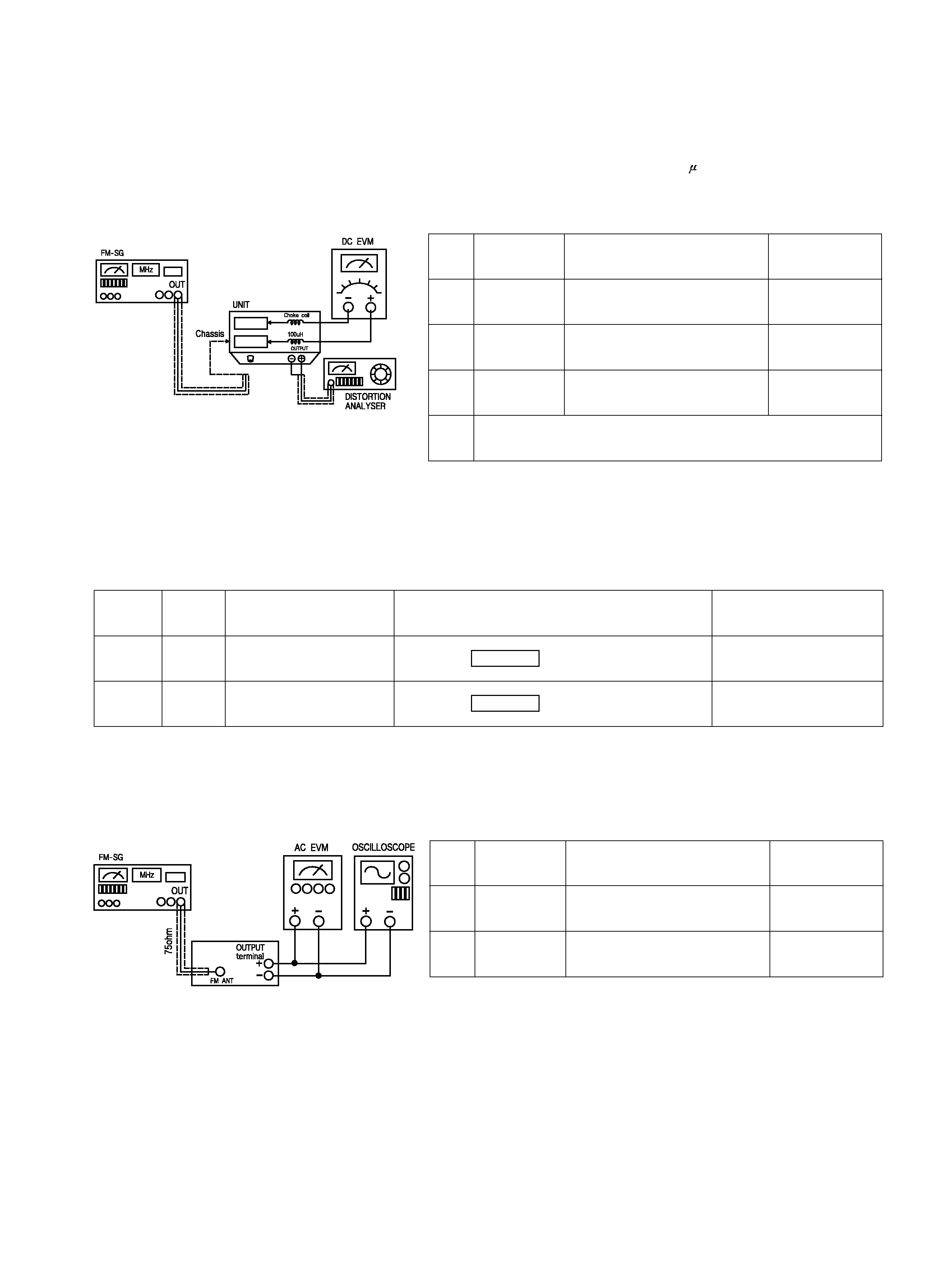
TEAC T-R670 Service Manual

Cover page of TEAC T-R670 Service Manual

Service Manual for TEAC T-R670, downloadable as a PDF file.

We also have owner's manual to this model.

Manual details

  • Immediate download after payment.
  • Delivered as a PDF file.
  • The manual has 9 pages
  • File size: 0.89 MB
  • Available language versions: English
  • Different language versions may vary sligthly in file size and page count.

We guarantee that...

  • our manuals are complete,
  • the manual includes circuit diagrams,
  • our manuals are checked with antivirus,
  • We'll issue refund if the manual is damaged, incomplete or unreadable (our refund policy)

Sample pages

Thumbnail of page 1Thumbnail of page 2Thumbnail of page 3Thumbnail of page 4
Thumbnail of page 5Thumbnail of page 6Thumbnail of page 7Thumbnail of page 8
Thumbnail of page 9
background image
T
T--R
R6
6770
0
SERVICE MANUAL
AM / FM Stereo Tuner
Effective : April, 2002
S-0056A
CONTENTS
1 SPECIFICATIONS
2
2 ADJUSTMENTS AND CHECKS
3
3 EXPLODED VIEWS AND PARTS LIST
6
4 PC BOARDS AND PARTS LIST
8
NOTES
PC boards shown are viewed from parts side.
The parts with no reference number or no parts number in the
exploded views are not supplied.
As regards the resistors and capacitors, refer to the circuit diagrams
contained in this manual.
£
Parts marked with this sign are safety critical components. They
must be replaced with identical components - refer to the appropriate
parts list and ensure exact replacement.
background image
1 SPECIFICATIONS
2
FM Tuner Section
(Without notes 98 MHz, 65 dBf)
Tuning Range: 87.5 MHz ­ 108.0 MHz (100 kHz steps)
Usable Sensitivity (IHF):
Mono: 11.2 dBf
50 dB Quieting Sensitivity:
Mono: 15 dBf
Stereo: 20 dBf
Total Harmonic Distortion (1 kHz):
Mono: 0.4%
Stereo: 0.5%
Frequency Response: 30 Hz ­ 15 kHz, +1/ ­1.5 dB
Stereo Separation (1 kHz): 40 dB
Signal-to-Noise Ratio:
Mono: 72 dB
Stereo: 70 dB
AM Tuner Section
Tuning Range: 530 kHz ­ 1,720 kHz (10 kHz steps)
Usable Sensitivity: 55 dB/m
Total Harmonic Distortion: 0.8% at 85 dB/m
Signal-to-Noise Ratio: 45 dB at 85 dB/m
General
Power Requirements: 120/230 V AC, 50-60 Hz
Power Consumption: 8 W
Dimensions (W x H x D): 435 x 102 x 270 mm
Weight (net): 3.6kg
Standard Accessories:
AM Loop Antenna x 1
FM T-type Antenna x 1
Matching Transformer x 1
Remote Control Unit (RC-789) x 1
Improvements may result in specifications and features
changing without notice.
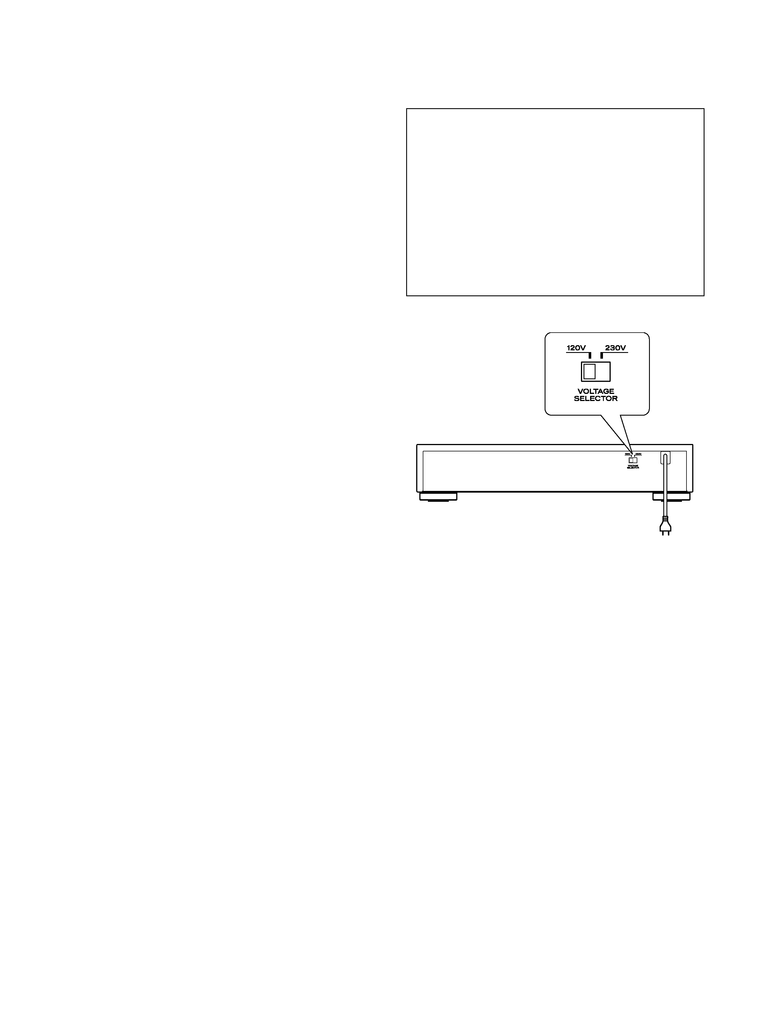
Voltage Conversion
(General export models only)
Be sure to remove the power cord from the AC outlet before
repositioning the voltage converter switch.
1. Locate the voltage selector on the rear panel.
2. Using a flat-bladed screwdriver, set to the appropriate
230V or 120V position according to your area.
IN NORTH AMERICA USE ONLY ON 120 V SUPPLY.
background image
2 ADJUSTMENTS AND CHECKS
3
ALIGNMENT INSTRUCTIONS
EQUIPMENT NEEDED:
AM Signal Generator
FM Signal Generator
Oscilloscope
VTVM(AC, DC)
Test loop antenna (AW Adjustment)
Dummy antenna (FM Adjustment)
Stereo signal modulator
Frequency counter
Distortion analyser
IMPORTANT
1. Check power-source voltage.
2. Set the function switch to band aligned.
3. Keep the signal input as low as possible to adjust accurately.
4. Modulation and modulation frequency.
Item
Modulation
Modulation frequency
Band
AM
30%
400Hz
FM
100%(75KHz Dev.)
400Hz
ADJUSTMENT POINT
MAIN PCB
T2
T3-2
T4
T5
TVR5
TVR4
TVR2
TVR1
TVR3
T1
TVC1
TVC2
TP1
L2
RF1
P5
P6
T1
T3-1
background image
4
1. AM TRACKING VOLTAGE ADJUSTMENTS
DC VOLTMETER ........................... CONNECT TO TEST POINT P5 and GND
NO.
Band
Frequency
Adjust for
Adjustment
1AM
530KHz
2.2V
T1
2AM
1720KHz
9.5V
TVC1
2. AM RF ADJUSTMENT
Signal Generator ........................ Connects to the AM ANT. Coil through the loop antenna.
Adjust for the indication of VTVM of the wave form of scope to be maximum.
BAND
Step
Frequency
Adjust for
Adjustment
1
630KHz
Maximum sensitivity
L2, T2
2
1420KHz
Maximum sensitivity
TVC2
3
Repeat steps 1 and 2 several times.
AM
NO.
Frequency
Adjust for
Adjustment
1
97.8MHz
L rejection
T4
2
P5
GND
3
97.8MHz
97.8MHz
TVR3
T5
L, R rejection
R rejection
3. FM 19kHz REJECTION ADJUSTMENT
background image
5
4. FM MONO DISTORTION ADJUSTMENT
DC VOLT METER ........................Connect to TP1(-), TP1(+) Through the choke coll (100 H)
Signal Generator........................Connect to FM ANT Jack (FM IN) through the dummy.
Distortion Meter .........................Connect to the output.
NO.
Frequency
Adjust for
Adjustment
1
97.8MHz
DC Voltmeter 0V
T3-1
2
97.8MHz
Minimum T.H.D
T3-2
3
5. FM/AM AUTO STOP LEVEL ADJUSTMENT
FM SIGNAL GENERATOR ........................Connect to FM ANT Jack (FM IN) through the dummy
AM SIGNAL GENERATOR.........................Connect to AM ANT, Coil through the Loop antenna
BAND
STEP
SIGNAL GENERATOR
Adjust for
Adjustment
1
97.8MHz 16dB
Display ON
TVR1
1
630KHz 74dB
Display ON
TVR2
AM
FM
TUNED
TUNED
4
Repeat steps 1 and 2 Several times.
97.8MHz
Minimum T.H.D
T1
TP1(-)
TP1(+)
NO.
Frequency
Adjust for
Adjustment
1
97.8MHz
L separation
TVR5
2
97.8MHz
TVR4
R separation
6. FM SEPARATION ADJUSTMENT

Reviews

There are no reviews of this manual yet.