TEAC SL-D90 Service Manual

Cover page of TEAC SL-D90 Service Manual

Service Manual for TEAC SL-D90, downloadable as a PDF file.

We also have owner's manual to this model.

Manual details

  • Immediate download after payment.
  • Delivered as a PDF file.
  • The manual has 29 pages
  • File size: 3.14 MB
  • Available language versions: English
  • Different language versions may vary sligthly in file size and page count.

We guarantee that...

  • our manuals are complete,
  • the manual includes circuit diagrams,
  • our manuals are checked with antivirus,
  • We'll issue refund if the manual is damaged, incomplete or unreadable (our refund policy)

Sample pages

Thumbnail of page 1Thumbnail of page 2Thumbnail of page 3Thumbnail of page 4
Thumbnail of page 5Thumbnail of page 6Thumbnail of page 7Thumbnail of page 8
Thumbnail of page 9
background image
SL-D90
AM/FM STEREO DIGITAL
1 SAFETY INFORMATION
PC board shown are viewed from parts side.
The parts with no reference number or no parts number
in the exploded views are not supplied.
As regards the resistors and capacitors, refer to the
circuit diagrams contained in this manual.
Parts marked with this sign are safety critical
components. they must be replaced with identical
ensure exact replacement.
!
components - refer to the appropriate parts list and
2 SPECIFICATIONS
4 EXPLODED VIEW AND PARTS LIST
5 PC BOARDS AND PARTS LISTS
6 WIRING DIAGRAM
7 INCLUDED ACCESSORIES
2
3
7
13
23
25
3 ADJUSTMENT AND CHECKS
4
RADIO WITH CD PLAYER
Parts of [ ] mark can be used only with the version designated.
[UL/CSA]: T/C
[ME/UNI]: EX/T [JIS]: DM [IT]: EUR
[HK]: UK/HKG
background image
1 SAFETY INFORMATION
USE OF CONTROLS OR ADJUSTMENT OR PERFORMANCE OF PROCEDURES OTHER THAN THOSE SPECIFIED HEREIN MAY RESULT IN
HAZARDOUS RADIATION EXPOSURE.
SAFETY INFORMATION
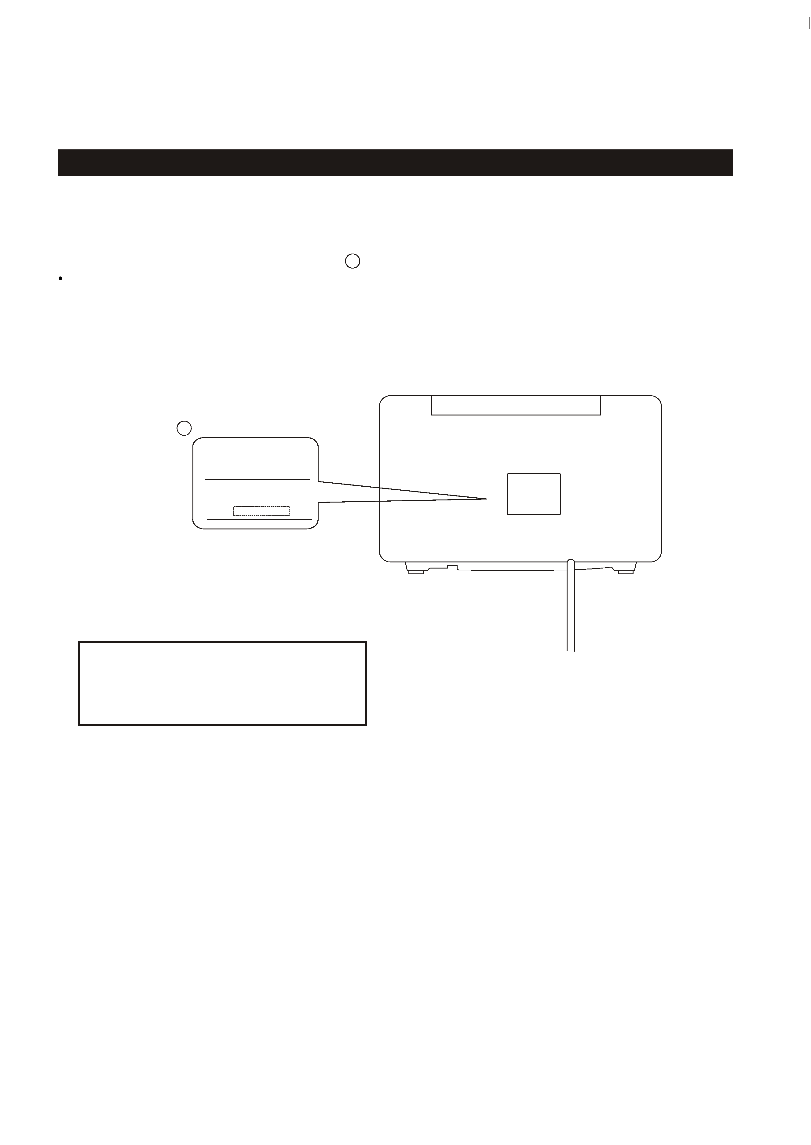
This product has been designed and manufactured according to FDA regulations " title 21, CFR, chapter 1,subchapter J,based on the
Radiation Control for Health and Safety Act of 1968" and is classified as class 1 laser product. There is not hazardous invisible laser
radiation during operation because invisible laser radiation emitted inside of this product is completely confined in the protective
housings. The label required in this regulation is shown
.
1
CAUTION
SL-D90
1
CERTIFICATION
THIS PRODUCT COMPLIES WITH DHHS
RULES 21 CFR SUBCHAPTER J APPLI-
CABLE AT DATE OF MANUFACTURE.
TEAC CORPORATION
3-7-3, NAKA-CHO, MUSASHINO-SHI, TOKYO, JAPAN
MANUFACTURED :
HKE
SERIAL
NO.
FOR U.S.A.
DO NOT REMOVE THE PROTECTIVE HOUSING USING SCREWDRIVER.
IF THIS PRODUCT DEVELOPS TROUBLE, MAKE A CONTACT WITH OUR SERICEMAN, AND DO NOT USE THE PRODUCT A TROUBLED STATE.
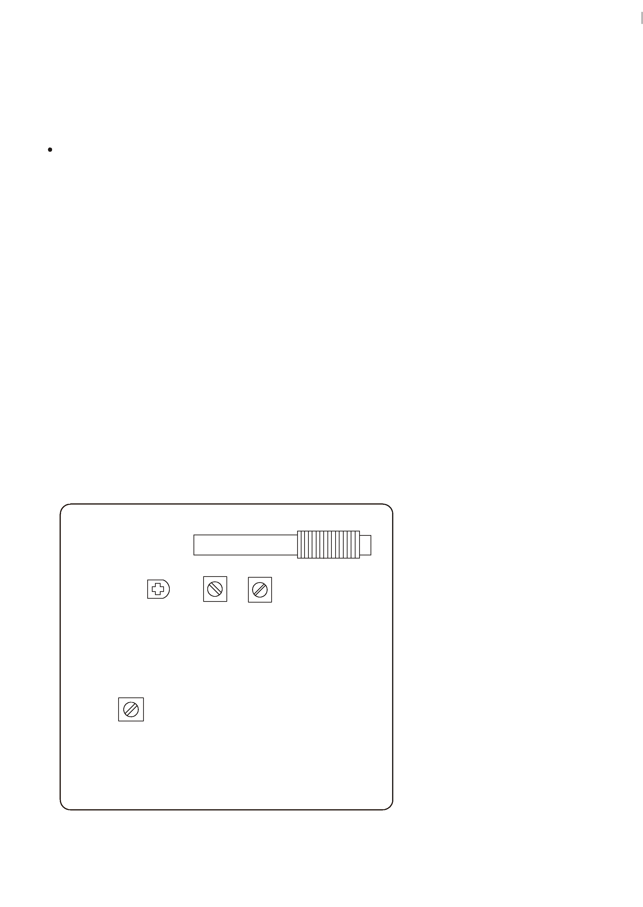
Optical pickup:
Type
: KSM-213CDM
Laser output : Lessthan 0.5 mW onthe objective lens
Wavelength
: 770 -795 nm
Manufacturer : SONY Corporation
2
background image
2 SPECIFICATIONS
SL-D90
Design and specifications are subject to change without notice.
TUNER Section
Frequency Range (FM):
Frequency Range (AM):
87.5MHz to 108.00 MHz
520kHz to 1710 kHz
Illustrations may differ slightly from production models.
3
Power Requirements:
Dimension (W x H x D ):
Weight:
Standard Accessories:
Warranty Card x 1
340 x 190 x 238.5 mm
5.15 kg (11-3/8 lb)
120V AC,60Hz (U.S.A/Canada model)
Power Consumption:
CD PLAYER Section
Frequency Response:
20 Hz to 20 kHz (+/- 1dB)
Wow and Flutter:
Unmeasurable
SPEAKER SYSTEM Section
Type:
1-way
Impedance:
8 ohms (L & R)
GENERAL
120/230V AC,50-60Hz (General export model)
40 W
Owner s Manual x 1
,
8 ohms (subwoofer)
(13-3/8 x 7-1/2 x 9-3/8) inches
Remote Control (RC-858) x 1
FM Lead-type Antenna x 1
Total Output Power :
20 W
background image
3 ADJUSTMENTS AND CHECKS
SL-D90
4
3-2 Adjustments and Test Points
Use a screwdriver with a plastic or ceramic grip for all adjustment.
3-1 TUNER SECTION
1. Set the function switch to the TUNER position.
2. Set the BAND switch to the AM position.
3. Connect the test loop antenna across the output of the signal generator.
4. Connect the oscilloscope to the PHONES JACK terminal.
3-1-1 AM adjustment
5. Set the signal generator as listed in the alignment chart.
1. Set the function switch to the TUNER position.
3. Connect the signal generator output through a 75 ohm dummy antenna to (ANT)
3-1-2 FM adjustment
2. Set the BAND switch to the FM position.
on TUNER PCB CN8
4. Connect the oscilloscope to the PHONES JACK terminal.
5. Set the signal generator as listed in the alignment chart.
AM ANT COIL
L4
L6
L5
TUNER PCB
TC1
L3
Fig. 3-2-1
background image
Fig. 3-2-3
AM Loop
Antenna
60cm
AM signal generator
SL-D90
PHONES
AM
AC voltmeter
1 k ohm
1 k ohm
3-2-2 AM Tuner
ITEM
SIGNAL GENERATOR SETTING
TUNER
ADJUSTMENTS
MEASURING
POINTS, RESULT
Audio
Modulation Frequency
Output
1. VOLTAGE
adjustment
2. IFT
adjustment
3. ANT coil
adjustment
4. TC1
adjustment
1710KHz
530 KHz
610KHz
30%
1KHz
1410KHz
L6
TC1
AM ant coil
Check
L4
VT
Repeat step 3
and 4
76 dBuV
8.0V
30%
30%
610KHz
SETTING
VT
1.5V
output level
Maximum
1KHz
610KHz
76 dBuV
610KHz
L3
Maximum
output level
1KHz
76 dBuV
1410KHz
Maximum
output level
SL-D90
5

Reviews

There are no reviews of this manual yet.