TEAC AD-600 Service Manual

Cover page of TEAC AD-600 Service Manual

Service Manual for TEAC AD-600, downloadable as a PDF file.

We also have owner's manual to this model.

Manual details

  • Immediate download after payment.
  • Delivered as a PDF file.
  • The manual has 26 pages
  • File size: 2.6 MB
  • Available language versions: English
  • Different language versions may vary sligthly in file size and page count.

We guarantee that...

  • our manuals are complete,
  • the manual includes circuit diagrams,
  • our manuals are checked with antivirus,
  • We'll issue refund if the manual is damaged, incomplete or unreadable (our refund policy)

Sample pages

Thumbnail of page 1Thumbnail of page 2Thumbnail of page 3Thumbnail of page 4
Thumbnail of page 5Thumbnail of page 6Thumbnail of page 7Thumbnail of page 8
Thumbnail of page 9
background image
A
AD
D--6
60
00
0
SERVICE MANUAL
Compact Disc Multi Player/Reverse Cassette Deck
Effective : November, 2000
S-0032A
CONTENTS
1 SAFETY INFORMATION
2
2 SPECIFICATIONS
3
3 ADJUSTMENTS AND CHECKS
4
4 EXPLODED VIEWS AND PARTS LIST
10
5 PC BOARDS AND PARTS LIST
16
6 INCLUDED ACCESSORIES
21
NOTES
PC boards shown are viewed from parts side.
Parts marked with * require longer delivery time.
The parts with no reference number or no parts number in the
exploded views are not supplied.
As regards the resistors and capacitors, refer to the circuit diagrams
contained in this manual.
£
Parts marked with this sign are safety critical components. They
must be replaced with identical components - refer to the appropriate
parts list and ensure exact replacement.
Parts of [ ] mark can be used only with the version designated.
£
background image
1 SAFETY INFORMATION
2
This product has been designed and manufactured according to
FDA regulations "title 21, CFR, chapter 1, subchapter J, based on
the Radiation Control for Health and Safety Act of 1968", and is
classified as a class 1 laser product. There is no hazardous
invisible laser radiation during operation because invisible laser
radiation emitted inside of this product is completely confined in
the protective housings.
The label required in this regulation is shown 1.
OCAUTION
USE OF CONTROLS OR ADJUSTMENT OR PERFORMANCE OF
PROCEDURES OTHER THAN THOSE SPECIFIED HEREIN MAY
RESULT IN HAZARDOUS RADIATION EXPOSURE.
CD
1 For U.S.A.
Optical pickup:
Type
: LTOH96MK or GH5C105A1APK
Manufacturer : SHARP Corporation
Laser output : Less than 0.5 mW on the objective lens
Wavelength
: 770-795 nm
Voltage Conversion
(General export models only)
Be sure to remove the power cord from the AC outlet before
repositioning the voltage converter switch.
1. Locate the voltage selector on the rear panel.
2. Using a flat-bladed screwdriver, set to the appropriate 230V or
120V position according to your area.
background image
2 SPECIFICATIONS
3
CD player section
(Audio)
Number of channels......................................................................2
Frequency response ....................................10 - 20,000 Hz ± 1 dB
Signal-to-noise ratio ..............................................................90 dB
Dynamic range ......................................................................90 dB
Total harmonic distortion ........................................0.02% (1 kHz)
Wow and flutter ..........................Unmeasurable (quartz accuracy)
Channel separation ................................................................70 dB
Output ................................................................................2 Vrms
Digital filter ................................8-times oversampling digital filter
(Signal format)
Sampling frequency ..........................................................44.1 kHz
D/A converter ................................................16-bit linear/channel
Channel bit rate ......................................................4.3218 Mb/sec.
Channel modulation code ........................................................EFM
Error correction ......................................................................CIRC
Cassette section
Track system ............................................4-track 2-channel stereo
Heads ....................................Record/playback x 1 (rotary reverse)
erase x 1
Type of tape ............................................Cassette tape C-60, C-90
Tape speed ................................................................4.76 cm/sec.
Motor ..............................................................DC servo motor x 1
Wow and flutter ..................................................0.08% (W. RMS)
Frequency response (overall) ........63 - 15,000 Hz ± 3 dB, chrome
63 - 14,000 Hz ± 3 dB, normal
Signal-to-noise ratio (overall) ........................................................
57 dB (Dolby NR off, 3% THD level, weighted)
66 dB (DOLBY NR on, over 5 kHz)
Fast winding time ..............................Approx. 120 sec. (with C-60)
Input ..........Line; 300mV (input impedance of 50 kohms or more)
Output ..........Line; 300mV (load impedance of 50 kohms or more)
Headphones; 5mW/33 ohms
General
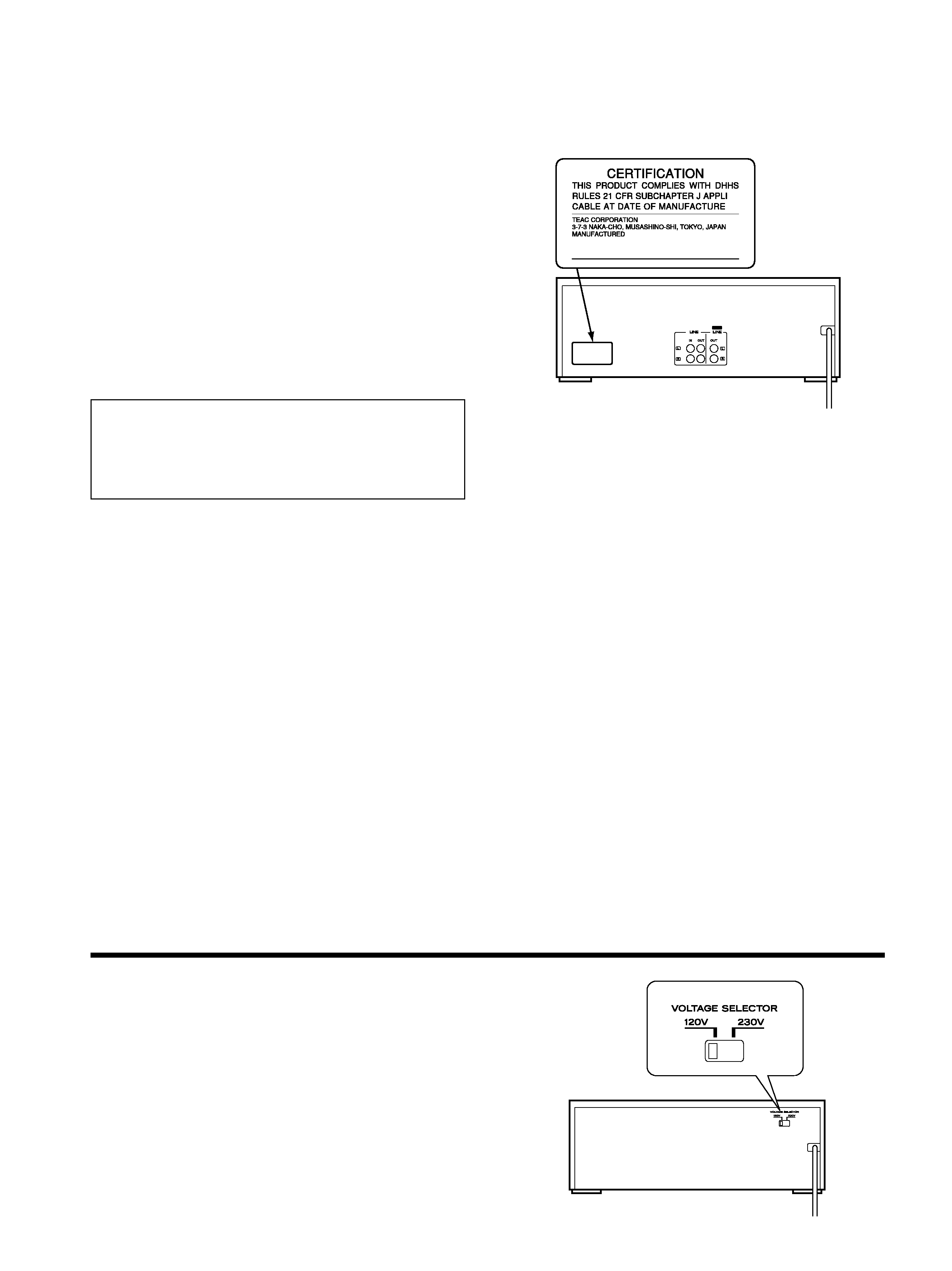
Power requirements ................................120/230 V AC, 50-60 Hz
(U.S.A./Canada/general export model)
230 V AC, 50 Hz (Europe/U.K. model)
Power consumption ..............................................................18 W
Dimensions (W x H x D) ................................435 x 147 x 293 mm
(17-1/8" x 5-13/16" x 11-9/16")
Weight..............................................................5.5 kg (12-5/8 lbs.)
Standard Accessories ............Wireless remote control RC-778 x 1
Pin plug cord x 2
Battery (SUM-3, "AA", "R6" type) x 2
Improvements may result in specification or feature changes
without notice.
Dolby noise reduction manufactured under license from Dolby
Laboratories Licensing Corporation.
"DOLBY" and the double-D symbol are trademarks of
Dolby Laboratories Licensing Corporation.
background image
3 ADJUSTMENTS AND CHECKS
4
3-1 CD PLAYER SECTION
3-1-1 Pitch control adjustment
1. Connect the frequency counter to the CD OUT.
2. Turn on a CD PITCH CONTROL switch at the stop mode.
3. Play the track 2 (1kHz, 0dB) of the MCD-111.
4. Set a CD PITCH CONTROL knob to a center, and adjust R811 of
CONTROL PCB so that the output becomes 1kHz.
5. When the CD PITCH CONTROL knob is rotated to the
side,
make sure the frequency becomes 880 Hz or lower, and make
sure it becomes 1,120 Hz or higher when the knob is rotated to
the
side.
3-1-2 Output level check
1. Connect the AC voltmeter to the CD OUT.
2. Play the track 2 (1kHz, 0dB) of the MCD-111, and check the
output level.
Specification: 2.0 0.5Vrms
3-1-3 Distortion check
1. Connect the distortion meter to the CD OUT.
2. Play the track 2 (1kHz, 0dB) of the MCD-111, and check the
distortion.
Specification: 0.03% or less (400Hz HPF
22kHz LPF)
3-1-4 Frequency response check
1. Play the track 3-6 (20Hz ­ 20kHz, 0dB) of the MCD-111, and
check that output level are within the specified values with
respect to the 1kHz reference level.
Specification: within
1dB
3-1-5 S/N check
1. Play the track 7 (non-signal) of the MCD-111, and check that
noise level are within the specified values with respect to the
1kHz reference level.
Specification: 83dB or more (22kHz LPF
IEC-A)
3-1-6 Channel separation check
1. Play the track 8 (L:1kHz / R:non-signal) of the MCD-111, and
check the leakage from Lch to Rch.
2. In the same way, play the track 10 (R:1kHz / L:non-signal) of
the MCD-111, and check the leakage from Rch to Lch.
Specification: 70dB or more (22kHz LPF
IEC-A)
background image
5
3-2 CASSETTE DECK SECTION
Before performing adjustments and checks clean and
demagnetize the entire tape path.
In general, adjustments and checks are made in the order of
Lch then Rch. Double REF. Nos. indicate Lch/Rch. (Example;
R181/R182)
0dB is referenced to 0.775V.
The AC voltmeter used in the procedures must have an input
impedance of 1M
or more.
Unless specified otherwise, adjustments and checks are made
in FWD direction.
Fig. 3-1 Adjustment locations
TAPE PCB
R291
R292
R293 R294
R030
R181 R182
L101
L102
L004
BN105
2
1
Frequency Counter

Reviews

There are no reviews of this manual yet.