PIONEER CORPORATION
4-1, Meguro 1-Chome, Meguro-ku, Tokyo 153-8654, Japan
PIONEER ELECTRONICS SERVICE INC.
P.O.Box 1760, Long Beach, CA 90801-1760 U.S.A.
PIONEER EUROPE N.V.
Haven 1087 Keetberglaan 1, 9120 Melsele, Belgium
PIONEER ELECTRONICS ASIACENTRE PTE.LTD. 253 Alexandra Road, #04-01, Singapore 159936
C PIONEER CORPORATION 2000
K-ZZB. MAR. 2000 Printed in Japan
ORDER NO.
CRT2465
CD PLAYER
YPM-2306ZF
WL
Service
Manual
FORD
- The CD mechanism employed in this model is one of S8.1 series.
CONTENTS
1. SAFETY INFORMATION ............................................2
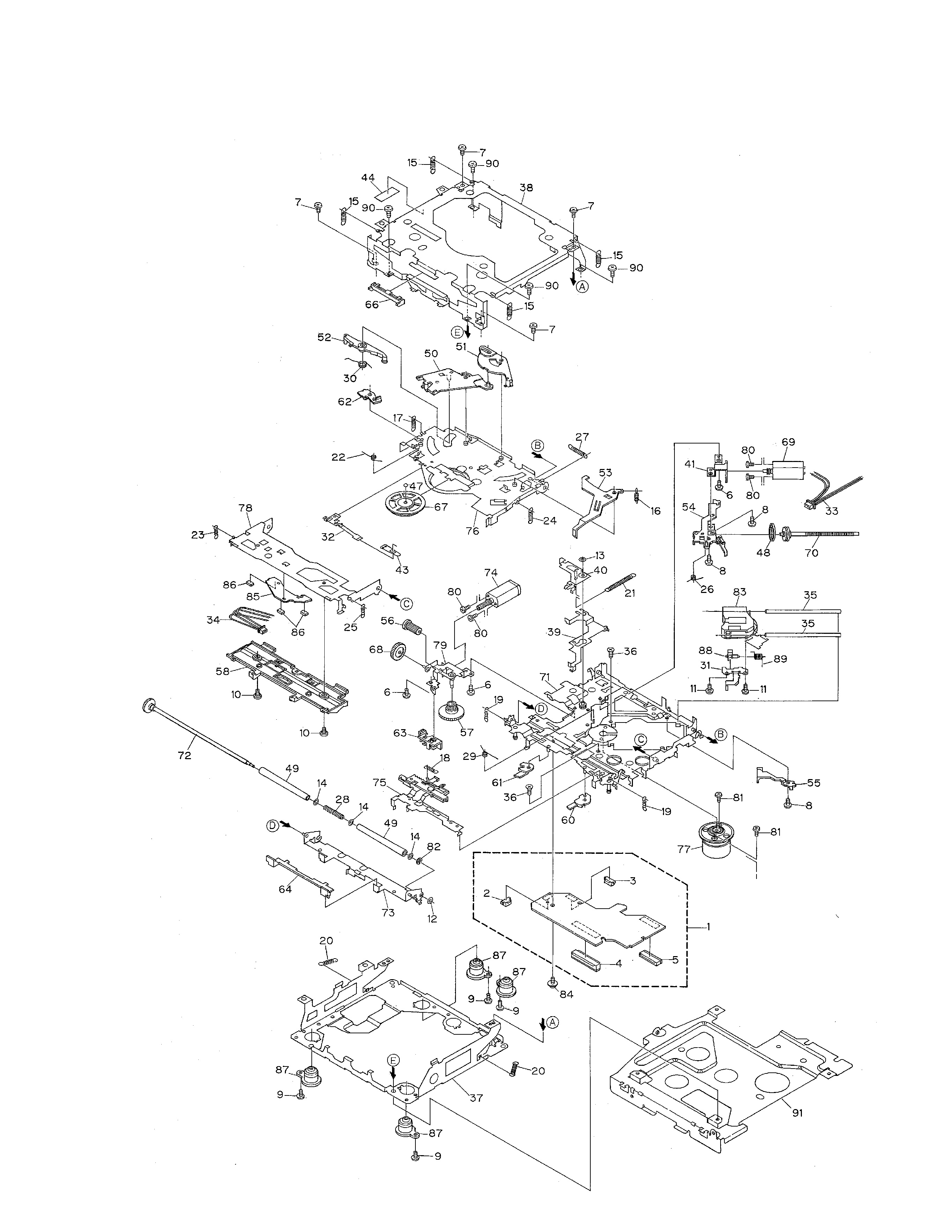
2. EXPLODED VIEWS AND PARTS LIST .......................3
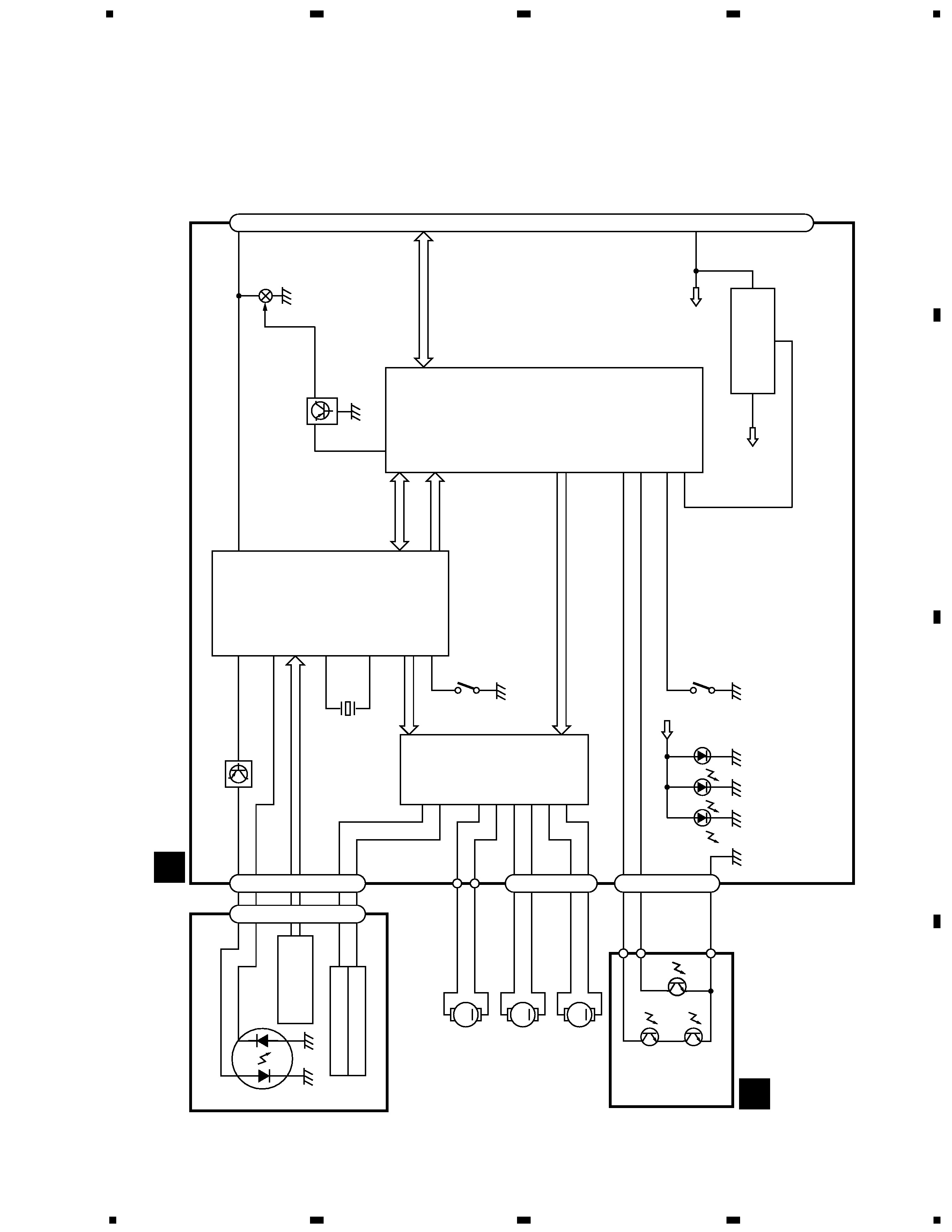
3. BLOCK DIAGRAM AND SCHEMATIC DIAGRAM .....5
4. PCB CONNECTION DIAGRAM ................................11
5. ELECTRICAL PARTS LIST ........................................14
6. ADJUSTMENT..........................................................16
7. GENERAL INFORMATION .......................................20
7.1 DIAGNOSIS ........................................................20
7.1.1 TEST MODE ..............................................20
7.1.2 DISASSEMBLY .........................................24
7.2 IC ........................................................................27
7.3 EXPLANATION ...................................................29
7.3.1 CIRCUIT DESCRIPTIONS .........................29
7.3.2 MECHANISM DESCRIPTIONS.................44