PIONEER CORPORATION 4-1, Meguro 1-chome, Meguro-ku, Tokyo 153-8654, Japan
PIONEER ELECTRONICS (USA) INC. P.O. Box 1760, Long Beach, CA 90801-1760, U.S.A.
PIONEER ELECTRONIC NV Haven 1087, Keetberglaan 1, 9120 Melsele, Belgium
PIONEER ELECTRONICS ASIACENTRE PTE. LTD. 253 Alexandra Road, #04-01, Singapore 159936
PIONEER CORPORATION 2001
c
ORDER NO.
X-NM1
RRV2522
1. SAFETY INFORMATION ...................................... 2
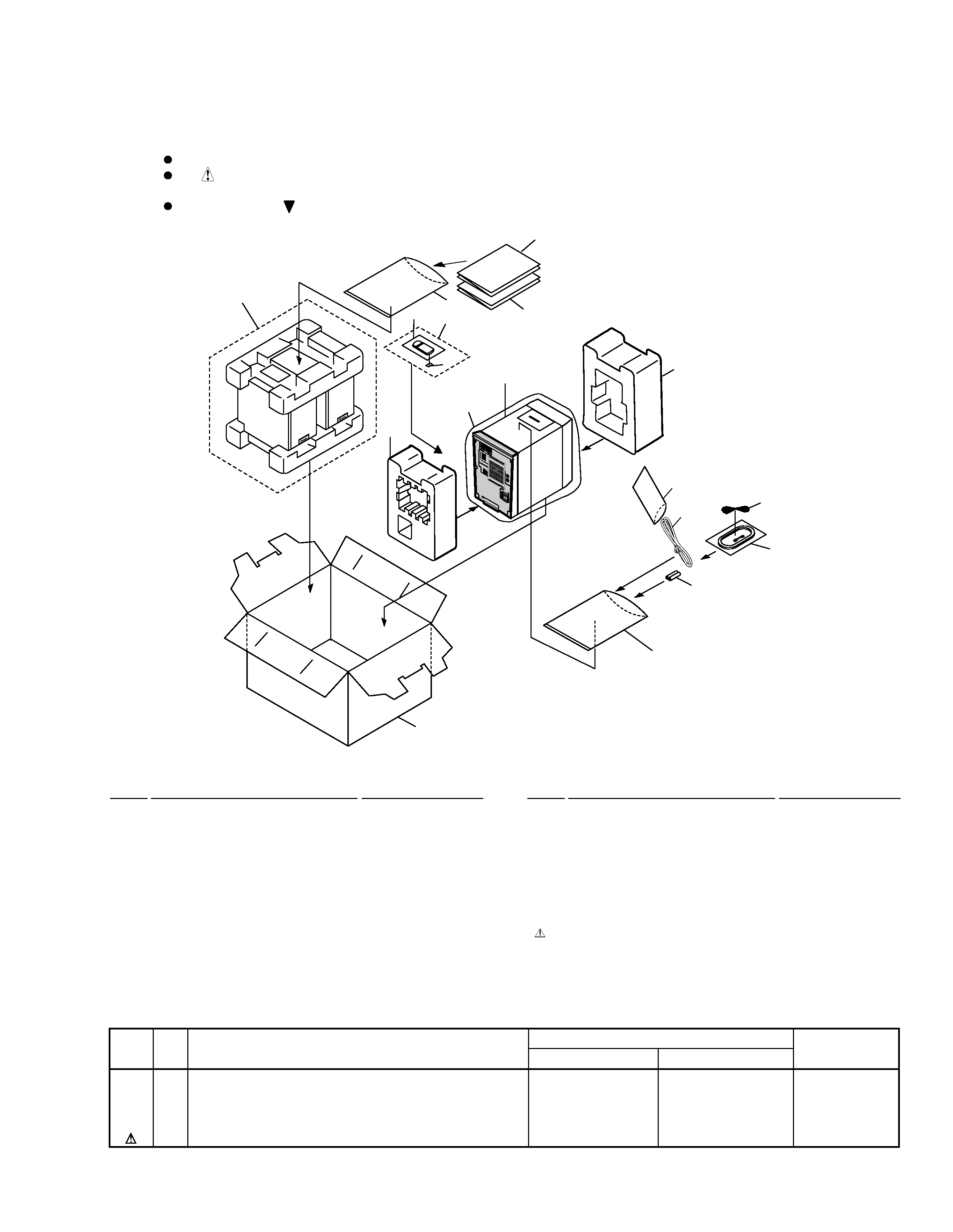
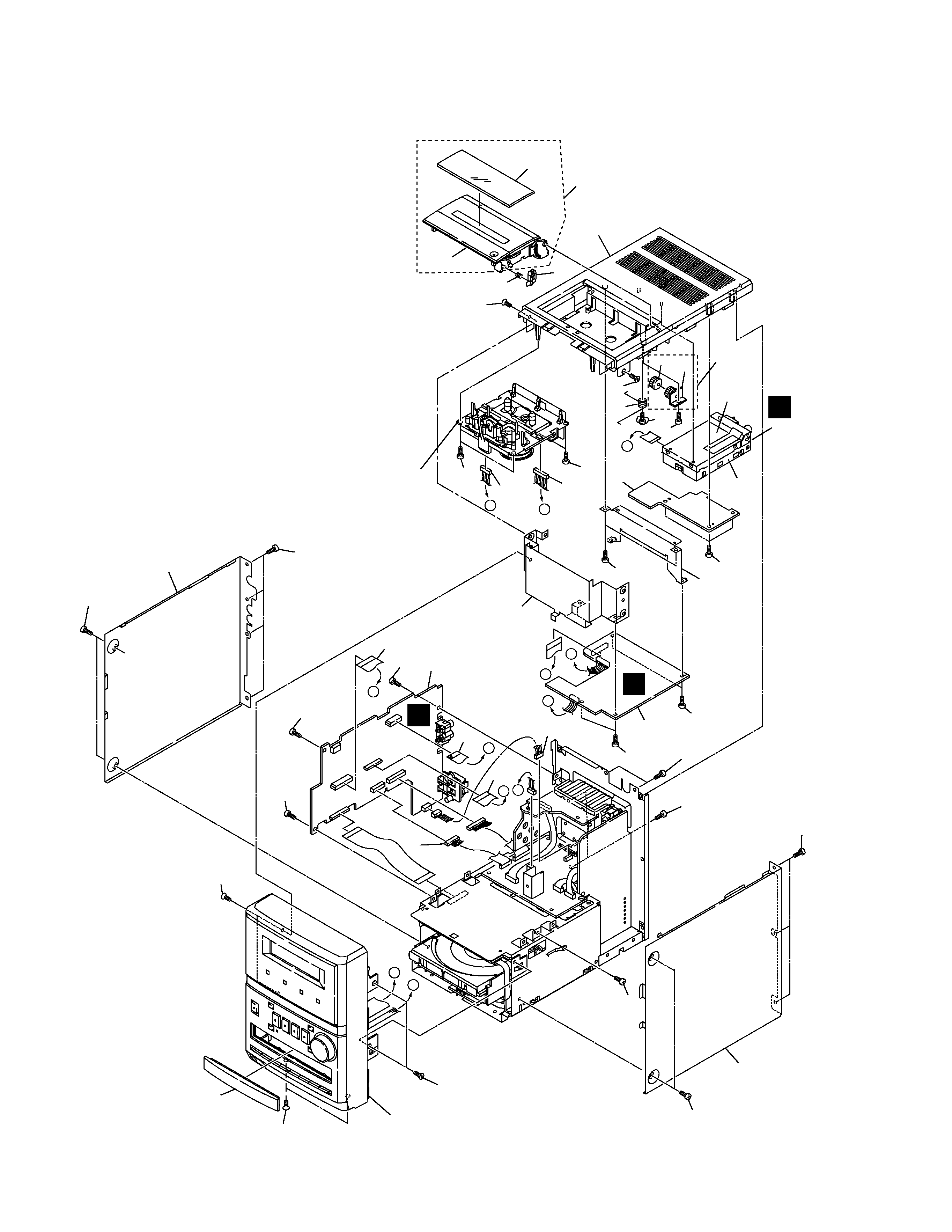
2. EXPLODED VIEWS AND PARTS LIST ............... 3
3. BLOCK DIAGRAM AND SCHEMATIC DIAGRAM ... 12
4. PCB CONNECTION DIAGRAM ......................... 32
5. PCB PARTS LIST ............................................... 46
6. ADJUSTMENT .................................................... 51
CONTENTS
T ZZK AUG. 2001 Printed in Japan
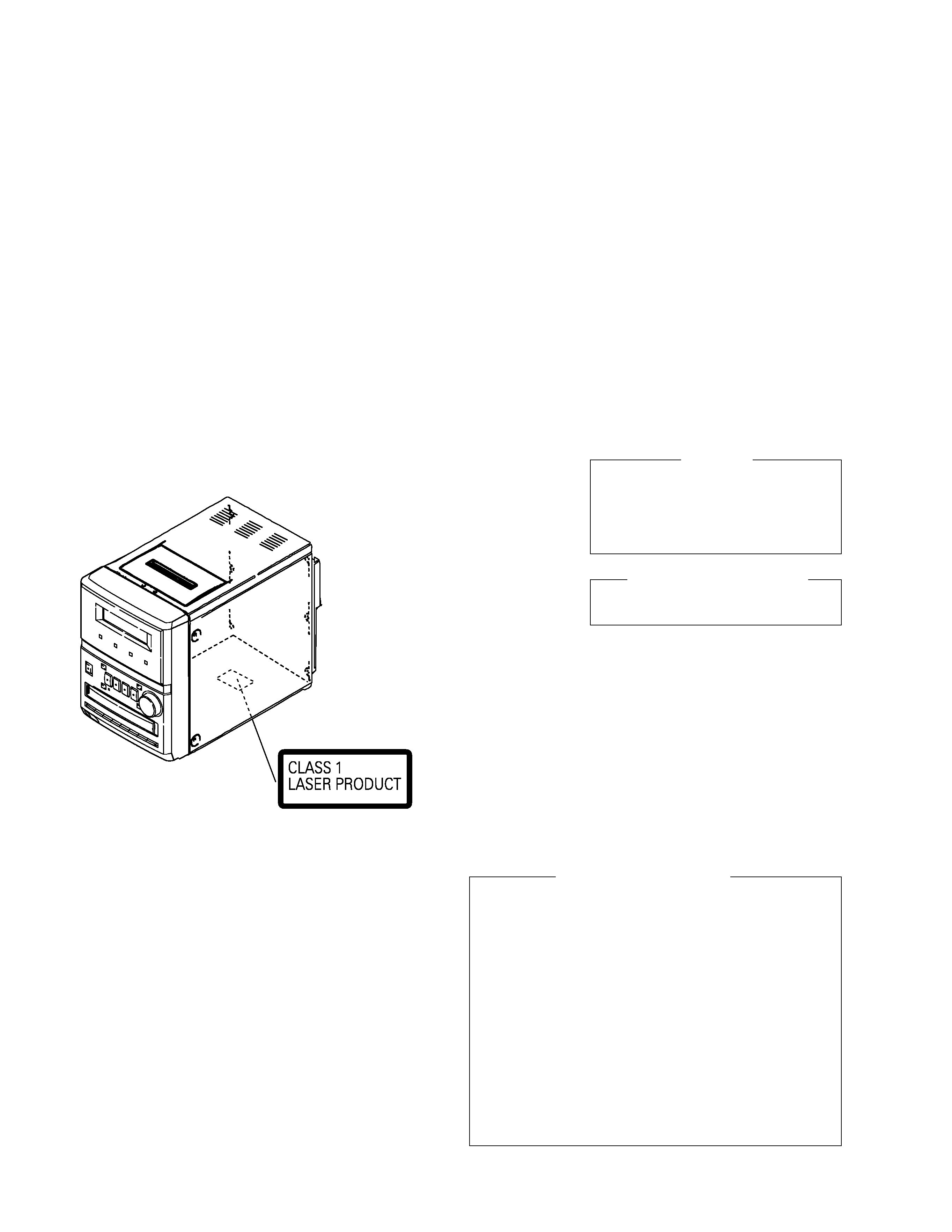
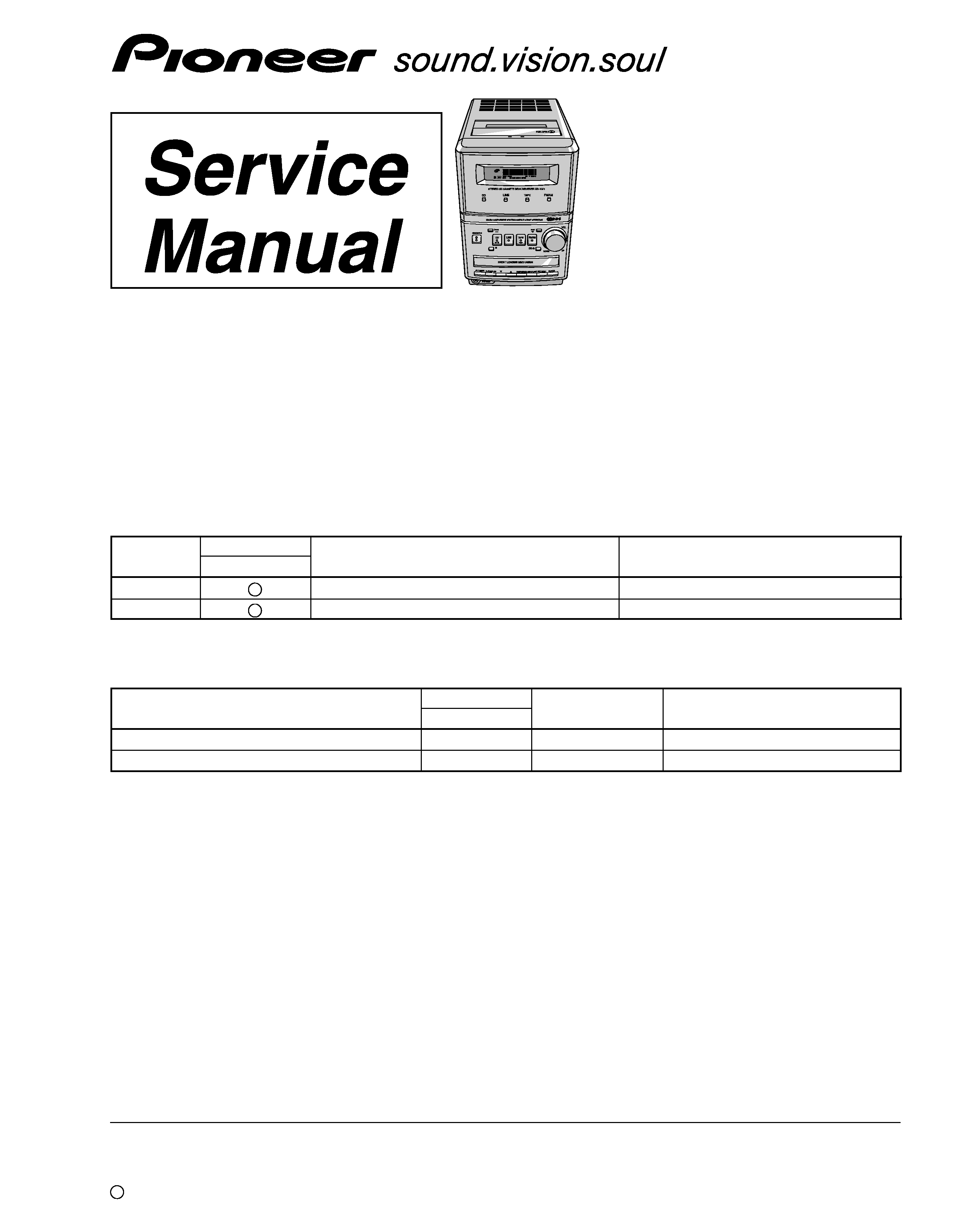
XR-NM1
COMPACT MINI COMPONENT
THIS MANUAL IS APPLICABLE TO THE FOLLOWING MODEL(S) AND TYPE(S).
Component
Model
Service manual
Remarks
X-NM1
STEREO CD CASSETTE DECK RECEIVER
XR-NM1
RRV2522
This manual.
SPEAKER SYSTEM
S-NM1
RRV2513
CD
Type
Model
Power Requirement
Remarks
XR-NM1
MYXCN
AC220-230V
NVXCN
AC230V
¶ X-NM1 is combination of the following components.
7. GENERAL INFORMATION ................................ 55
7.1 DIAGNOSIS .................................................. 55
7.1.1 ERROR DISPLAY .................................. 55
7.1.2 POWER ON SEQUENCE ...................... 56
7.1.3 CIRCUIT DESCRIPTION ....................... 57
7.1.4 DISASSEMBLY/ASSEMBLY .................. 58
7.2 PARTS .......................................................... 62
7.2.1 IC ............................................................ 62
7.2.2 DISPLAY ................................................. 65
8. PANEL FACILITIES AND SPECIFICATIONS ....... 68