PIONEER VSX-D859TX/BXJI Owner's Manual

Cover page of PIONEER VSX-D859TX/BXJI Owner's Manual

Owner's Manual for PIONEER VSX-D859TX/BXJI, downloadable as a PDF file.

We also have service manual to this model.

Manual details

  • Immediate download after payment.
  • Delivered as a PDF file.
  • The manual has 92 pages
  • File size: 7.52 MB
  • Available language versions: English, Spanish
  • Different language versions may vary sligthly in file size and page count.

We guarantee that...

  • our manuals are complete,
  • our manuals are checked with antivirus,
  • We'll issue refund if the manual is damaged, incomplete or unreadable (our refund policy)

Sample pages

Thumbnail of page 1Thumbnail of page 2Thumbnail of page 3Thumbnail of page 4
Thumbnail of page 5Thumbnail of page 6Thumbnail of page 7Thumbnail of page 8
Thumbnail of page 9
background image
Operating Instructions
AUDIO/VIDEO
MULTI-CHANNEL RECEIVER
VSX-D859TX
VSX-D859TXG
background image
Operating Instructions
AUDIO/VIDEO
MULTI-CHANNEL RECEIVER
VSX-D859TX
VSX-D859TXG
background image
2
En
Thank you for buying this Pioneer product.
Please read through these operating instructions
so you will know how to operate your model prop-
erly. After you have finished reading the instruc-
tions, put them away in a safe place for future
reference.
WARNING: TO PREVENT FIRE OR SHOCK
HAZARD, DO NOT EXPOSE THIS APPLIANCE TO
RAIN OR MOISTURE.
THE OFF/ON BUTTON IS SECONDARY CONNECTED
AND THEREFORE DOES NOT SEPARATE THE UNIT
FROM MAINS POWER IN STANDBY POSITION.
If the socket outlets on the associated equipment
are not suitable for the plug supplied with the
product the plug must be removed and
appropriate one fitted.
The cut-off plug must be disposed of as an
electrical shock hazard could exist if connected to
a socket outlet.
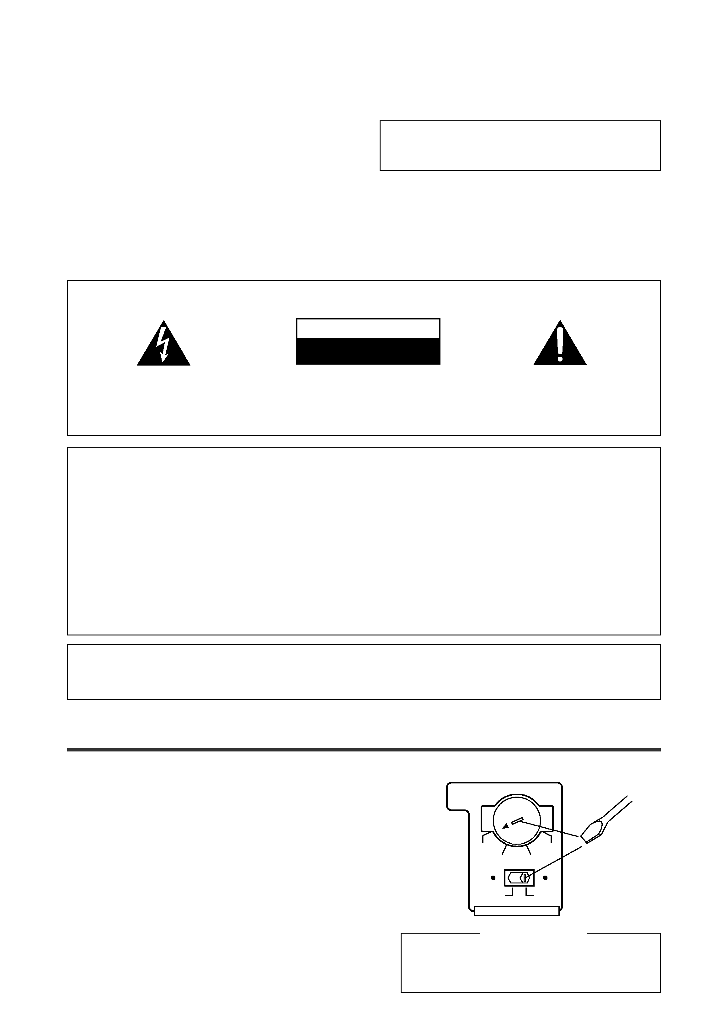
TWO VOLTAGE SELECTOR SWITCHES (Except Singaporean model)
Only multi-voltage model is provided with this switch. Mains
voltages in Saudi Arabia are 127 V and 220 V only. Never use
this model with the 110 V setting in Saudi Arabia.
The line voltage selector switches are on the rear panel. Check that they
are set properly before plugging the power cord into the household wall
socket. If the voltage is not properly set or if you move to an area where
the voltage requirements differ, adjust the selector switches as follows.
1. Use a medium-size screwdriver.
2. First, insert the screwdriver in the groove of the voltage
selector upper, and adjust so that the tip of the groove
points to the voltage value of your area.
3. Next, insert the screwdriver in the groove of the voltage
selector lower and adjust until the voltage is the same
as at the right.
Medium-size
screwdriver
220V
240V
110V 120V-127V
110V
120V-127V
220V
240V
TWO VOLTAGE SELECTORS
IMPORTANT
The lightning flash with arrowhead symbol,
within an equilateral triangle, is intended to
alert the user to the presence of uninsulated
"dangerous voltage" within the product's
enclosure that may be of sufficient magnitude
to constitute a risk of electric shock to persons.
The exclamation point within an equilateral
triangle is intended to alert the user to the
presence
of
important
operating
and
maintenance (servicing) instructions in the
literature accompanying the appliance.
CAUTION:
TO PREVENT THE RISK OF ELECTRIC SHOCK,
DO NOT REMOVE COVER (OR BACK).
NO
USER-SERVICEABLE PARTS INSIDE.
REFER
SERVICING
TO
QUALIFIED
SERVICE
PERSONNEL.
RISK OF ELECTRIC SHOCK
DO NOT OPEN
CAUTION
Information to User
Alteration or modifications carried out without appropriate authorization may invalidate the user's right to
operate the equipment.
NOTE: This equipment has been tested and found to comply with the limits for a Class B digital device,
pursuant to Part 15 of the FCC Rules. These limits are designed to provide reasonable protection against harm-
ful interference in a residential installation. This equipment generates, uses, and can radiate radio frequency
energy and, if not installed and used in accordance with the instructions, may cause harmful interference to
radio communications. However, there is no guarantee that interference will not occur in a particular installa-
tion. If this equipment does cause harmful interference to radio or television reception, which can be deter-
mined by turning the equipment off and on, the user is encouraged to try to correct the interference by one or
more of the following measures:
­ Reorient or relocate the receiving antenna.
­ Increase the separation between the equipment and receiver.
­ Connect the equipment into an outlet on a circuit different from that to which the receiver is connected.
­ Consult the dealer or an experienced radio/TV technician for help.
CAUTION 220 V
Power source voltage is factory adjusted 220
volts. If your area is different, change voltage
selectors settings.
background image
3
En
Quick Start Guide
(not a PCM-only output)
This is a quick guide to setting up your new receiver so you can get home theater surround sound. For
more details on any of the information presented here check the main section of the manual.
Before making or changing the connections, switch off the power and disconnect the power cord
from the AC wall outlet.
1
1
1
1
1 Hooking Up Your DVD Player & TV
In order to use Dolby Digital/DTS/MPEG soundtracks which are at the heart of home theater you need to
hook up your DVD player with digital audio connections. You can do this by either a coaxial or an optical
connection, you don't need to do both. The quality of these two types of connections is the same but
since some digital components only have one type of digital terminal you need to figure out which yours
has and hook it up to the appropriate terminal on the receiver. In order to do this you will need the proper
cable. For coaxial connections you can use a regular RCA stereo cord or the specially-made coaxial cords,
they have the same type of plugs. For optical connections you will need a special optical cord which you
can buy at your local stereo store. Also hook up the video connection of your DVD player, the analog audio
(for recording the audio on DVDs, use regular RCA stereo cords), and your TV (it's easiest to use regular
composite RCA video cords) as shown below. It is important that you hook up your TV (or monitor) in
order to see a video image as well as the on screen displays (OSDs) shown by the VSX-D859TX/D859TXG
(for more on p.16). We also recommend hooking up all your digital components to analog audio jacks as
well. For this you can use regular RCA stereo cords.
Digital Connection
If your DVD player has a coaxial terminal (not a PCM-only output) for the audio out hook up the receiver
using that terminal. This is the best scenario, as you will be able to follow the default settings of this
receiver and won't need to assign the digital inputs. If your DVD player has an optical terminal (not a PCM-
only output) for the audio out you can hook up the receiver using that terminal. You will need to assign the digital
input (tell the receiver which input you put your DVD digital audio into). See p. 5 for this.
For either optical or
coaxial connections follow the diagram below to make a digital connection between your DVD player and
this receiver.
DVD player
OUTPUT
DIGITAL
STEREO
L
R
ANALOG
VIDEO
OUT
VIDEO
VIDEO INPUT
L
R
L
R
RCA video cord
RCA video cord
RCA stereo cord
optical cord
coaxial cord
background image
4
En
Quick Start Guide
2
2
2
2
2 Speaker Connections
Home theater is designed to be set up with five, or seven speakers (front left & right; center; surround left &
right; and, optimally, surround back left & right) and a subwoofer but you can use this receiver with fewer
speakers.
Hook up the speakers you have to the SPEAKERS A terminals on the back of the receiver. If you only have two
speakers hook them up as FRONT. If you have three, hook up the single speaker as CENTER. Follow the
diagram below in order to hook up all your speakers. A center speaker is very important for watching films
because the dialog comes from the center speaker in digital soundtracks. If you do not have a CENTER
speaker you must tell the receiver the CENTER channel is OFF or when you listen to digital soundtracks
you won't hear any dialog. Use the instructions on p. 33 ­ 34 in order to do this.
Follow the diagram below to hook up an additional amplifier in order to use surround back speakers. These
speakers are important to hear all the sound channels on new, eight channel home theater DVDs. The diagram
below also explains how to hook up a subwoofer which provides realistic bass sounds.
Make sure you connect the speaker on the right to the right terminal and the speaker on the left to the left
terminal. Also make sure the positive and negative (+/­) terminals on the amplifier match those on the speakers.
3
3
3
3
3 Setting up the Remote Control & Unit
1 Put the batteries in the REMOTE CONTROL. (See p. 9)
2 Plug the main unit into a AC wall outlet.
There are two buttons that affect the power. ON/OFF actually turns the power on/off and STANDBY/
ON toggles between standby mode and the receiver fully on. When in standby mode you can turn the
unit on with the remote control.
Surround
speaker
(Right)
Surround back
speaker (Right)
Surround back
speaker (Left)
INPUT
Powered
subwoofer
Surround
speaker
(Left)
Front
speaker (A)
(Left)
Front
speaker (A)
(Right)
TV/monitor
Center
speaker
Additional Amplifier (See p. 20)
background image
5
En
4
4
4
4
4 Digital Input Assignment
This is only necessary if you did not hook up your DVD to DIGITAL IN 1, as in the diagram on p. 3.
Quick Start Guide
1 Set the remote control slide switch
to SETUP.
Also make sure your TV is on and set to the
receiver.
· When you're done setting up the receiver,
remember to set the slide switch back to
USE.
2 Press the SYSTEM SETUP button.
You should see the following display on your
TV.
[
[
Ass g
in S e t u p ]
Se t u p ]
Su r r ou n d
[
Re n ame ]
Fu n c t i o n
[
]
EX I T
· You can escape from this screen at any time
by pressing the SYSTEM SETUP button
again. None of the settings you made will be
entered in this case.
3 Assign Set up should be selected, if
it isn't use the
5¥ buttons to
select it. Press ENTER.
You should see the following display on your
TV.
[
[
D igi t a l - I n Se l e c t
Se l e c t
]
nn e l
n
I
]
Mu l t i
Comp o
a
Ch
[
-I n
]
e
nn t
[
]
EX I T
4 Digital in Select should be selected,
if it isn't use the
5¥ buttons to
select it. Press ENTER.
You should see the following display on your
TV.
[
D igi t a l - i
DVD / LD
D igi ta l - i
D igi ta l - 1
nS e l e c t
]
[ DVD / LD ]
[
D igi t a l - i
CD
CD
D igi ta l - 2
]
[
D igi t a l - i
-R
RF
I N
D igi ta l - 3
]
[
D igi t a l - i
TV/SAT
D igi ta l - 4
]
[
]
EX I T
5 Choose the Digital-3 (or the digital
in jack you connected your DVD to
on page 3) you hooked up your DVD
player to and assign "DVD/LD" to it.
1 Use the
5¥ buttons to choose the Digital-3
and press ENTER.
[
D igi t a l - i
DVD / LD
DVD / LD
D igi ta l - i
D igi ta l - 1
nS e l e c t
]
[
D igi t a l - i
CD
D igi ta l - 2
]
[
D igi t a l - i
D igi ta l - 3
]
[
D igi t a l - i
TV/SAT
D igi ta l - 4
]
[
]
EX I T
[ DVD / LD ]
RF
I N
2 Use the
5¥ buttons to choose the DVD/LD
setting and press ENTER.
[
D igi t a l - i
OF F
D igi ta l - i
D igi ta l - 1
nS e l e c t
]
[ DVD / LD ]
[
D igi t a l - i
CD
D igi ta l - 2
]
D igi t a l - i
D igi ta l - 3
[
D igi t a l - i
TV/SAT
D igi ta l - 4
]
[
]
EX I T
[ DVD / LD ]
RF
I N
6 Select EXIT with
5¥ buttons and
press ENTER to return to the Assign
Setup menu.
[
[
D igi ta l - I n Se l e c t
Se l e c t
]
nn e l
n
I
]
Mu l t i
Comp o
a
Ch
[
-I n
]
e
nn t
[
]
EX I T
7 Select EXIT with
5¥ buttons and
press ENTER to return to the
System Setup menu.
S0URCE
DVD/LD
TV/SAT
VCR1/
DVR
VCR2
CD
CD-R/
TUNER
TVCONT
RECEIVER
USE
SETUP
MULTI
OPERATION
SYSTEM
OFF
Î
MULTI CONTROL
1
S0URCE
DVD/LD
TV/SAT
VCR1/
DVR
VCR2
CD
CD-R/
TUNER
TVCONT
RECEIVER
USE
SETUP
MULTI
OPERATION
SYSTEM
OFF
Î
MULTI CONTROL
1
MENU
ENTER
STEREO/
DIRECT
DSP
THX
LIGHT
/DTS/MPEG
MUTE
FUNCTION
REMOTE SETUP
SYSTEM SETUP
INPUT
ATT
ADVANCED
MIDNIGHT
MULTI CH
INPUT
STANDARD
DIGITAL
NR
EFFECT/
CH SEL
SIGNAL
SELECT
+
­
3-7
2

Reviews

There are no reviews of this manual yet.