PIONEER VSX-AX10AI-G/DLT Service Manual

Cover page of PIONEER VSX-AX10AI-G/DLT Service Manual

Service Manual for PIONEER VSX-AX10AI-G/DLT, downloadable as a PDF file.

We also have owner's manual to this model.

Manual details

  • Immediate download after payment.
  • Delivered as a PDF file.
  • The manual has 206 pages
  • File size: 26.62 MB
  • Available language versions: English
  • Different language versions may vary sligthly in file size and page count.

We guarantee that...

  • our manuals are complete,
  • the manual includes circuit diagrams,
  • our manuals are checked with antivirus,
  • We'll issue refund if the manual is damaged, incomplete or unreadable (our refund policy)

Sample pages

Thumbnail of page 1Thumbnail of page 2Thumbnail of page 3Thumbnail of page 4
Thumbnail of page 5Thumbnail of page 6Thumbnail of page 7Thumbnail of page 8
Thumbnail of page 9
background image
ORDER NO.
PIONEER CORPORATION 4-1, Meguro 1-chome, Meguro-ku, Tokyo 153-8654, Japan
PIONEER ELECTRONICS (USA) INC. P.O. Box 1760, Long Beach, CA 90801-1760, U.S.A.
PIONEER EUROPE NV Haven 1087, Keetberglaan 1, 9120 Melsele, Belgium
PIONEER ELECTRONICS ASIACENTRE PTE. LTD. 253 Alexandra Road, #04-01, Singapore 159936
PIONEER CORPORATION 2003
STANDBY/ON
OFF
ON
STANDBY
DVD/LD
TV/DVD
SAT
VIDEO
VIDEO
AUDIO
DVR/VCR1
VCR2
VCR3
CD
TUNER
PHONO
CD-R/
TAPE1/MD
MULTI CH
INPUT
LISTENING MODE SELECTOR
TURN/PUSH
MASTER VOLUME
INPUT SELECTOR
VSX-59TXi
AUDIO/VIDEO MULTI-CHANNEL RECEIVER
VSX-59TXi
RRV2856
AUDIO/VIDEO MULTI-CHANNEL RECEIVER
VSX-59TXi
THIS MANUAL IS APPLICABLE TO THE FOLLOWING MODEL(S) AND TYPE(S).
Model
Type
Power Requirement
Remarks
VSX-59TXi
KU/CA
AC120V
For details, refer to "Important symbols for good services" .
T-ZZR DEC. 2003 printed in Japan
background image
VSX-59TXi
2
1234
123
4
C
D
F
A
B
E
SAFETY INFORMATION
This service manual is intended for qualified service technicians it is not meant for the casual do-it-
yourselfer. Qualified technicians have the necessary test equipment and tools, and have been trained
to properly and safely repair complex products such as those covered by this manual.
;
Improperly performed repairs can adversely affect the safety and reliability of the product and
mayvoid the warranty. If you are not qualified to perform the repair of this product properly and safely,
youshould not risk trying to do so and refer the repair to a qualified service technician.
WARNING
This product contains lead in solder and certain electrical parts contain chemicals which are known to the state of California to cause
cancer, birth defects or other reproductive harm.
Health & Safety Code Section 25249.6 ­ Proposition 65
NOTICE
(FOR CANADIAN MODEL ONLY)
Fuse symbols
(fast operating fuse) and/or
(slow operating fuse) on PCB indicate that replacement par ts must
be of identical designation.
REMARQUE
(POUR MODÈLE CANADIEN SEULEMENT)
Les symboles de fusible
(fusible de type rapide) et/ou
(fusible de type lent) sur CCI indiquent que les pièces
de remplacement doivent avoir la même désignation.
ANY MEASUREMENTS NOT WITHIN THE LIMITS
OUTLINED ABOVE ARE INDICATIVE OF A POTENTIAL
SHOCK HAZARD AND MUST BE CORRECTED BEFORE
RETURNING THE APPLIANCE TO THE CUSTOMER.
2. PRODUCT SAFETY NOTICE
Many electrical and mechanical parts in the appliance
have special safety related characteristics. These are
often not evident from visual inspection nor the protection
afforded by them necessarily can be obtained by using
replacement components rated for voltage, wattage, etc.
Replacement par ts which have these special safety
characteristics are identified in this Service Manual.
Electrical components having such features are identified
by marking with a
on the schematics and on the parts list
in this Service Manual.
The use of a substitute replacement component which does
not have the same safety characteristics as the PIONEER
recommended replacement one, shown in the parts list in
this Service Manual, may create shock, fire, or other hazards.
Product Safety is continuously under review and new
instructions are issued from time to time. For the latest
information, always consult the current PIONEER Service
Manual. A subscription to, or additional copies of, PIONEER
Service Manual may be obtained at a nominal charge from
PIONEER.
1. SAFETY PRECAUTIONS
The following check should be performed for the
continued protection of the customer and ser vice
technician.
LEAKAGE CURRENT CHECK
Measure leakage current to a known earth ground (water
pipe, conduit, etc.) by connecting a leakage current tester
such as Simpson Model 229-2 or equivalent between the
earth ground and all exposed metal parts of the appliance
(input/output terminals, screwheads, metal overlays, control
shaft, etc.). Plug the AC line cord of the appliance directly
into a 120V AC 60Hz outlet and turn the AC power switch
on. Any current measured must not exceed 0.5mA.
(FOR USA MODEL ONLY)
Leakage
current
tester
Reading should
not be above
0.5mA
Device
under
test
Test all
exposed metal
surfaces
Also test with
plug reversed
(Using AC adapter
plug as required)
Earth
ground
AC Leakage Test
background image
VSX-59TXi
3
5
678
56
7
8
C
D
F
A
B
E
[ Important symbols for good services ]
In this manual, the symbols shown-below indicate that adjustments, settings or cleaning should be made securely.
When you find the procedures bearing any of the symbols, be sure to fulfill them:
2. Adjustments
To keep the original performances of the product, optimum adjustments or specification confirmation is indispensable.
In accordance with the procedures or instructions described in this manual, adjustments should be performed.
3. Cleaning
For optical pickups, tape-deck heads, lenses and mirrors used in projection monitors, and other parts requiring cleaning,
proper cleaning should be performed to restore their performances.
5. Lubricants, glues, and replacement parts
Appropriately applying grease or glue can maintain the product performances. But improper lubrication or applying
glue may lead to failures or troubles in the product. By following the instructions in this manual, be sure to apply the
prescribed grease or glue to proper portions by the appropriate amount.For replacement parts or tools, the prescribed
ones should be used.
4. Shipping mode and shipping screws
To protect the product from damages or failures that may be caused during transit, the shipping mode should be set or
the shipping screws should be installed before shipping out in accordance with this manual, if necessary.
1. Product safety
You should conform to the regulations governing the product (safety, radio and noise, and other regulations), and
should keep the safety during servicing by following the safety instructions described in this manual.
background image
VSX-59TXi
4
1234
123
4
C
D
F
A
B
E
CONTENTS
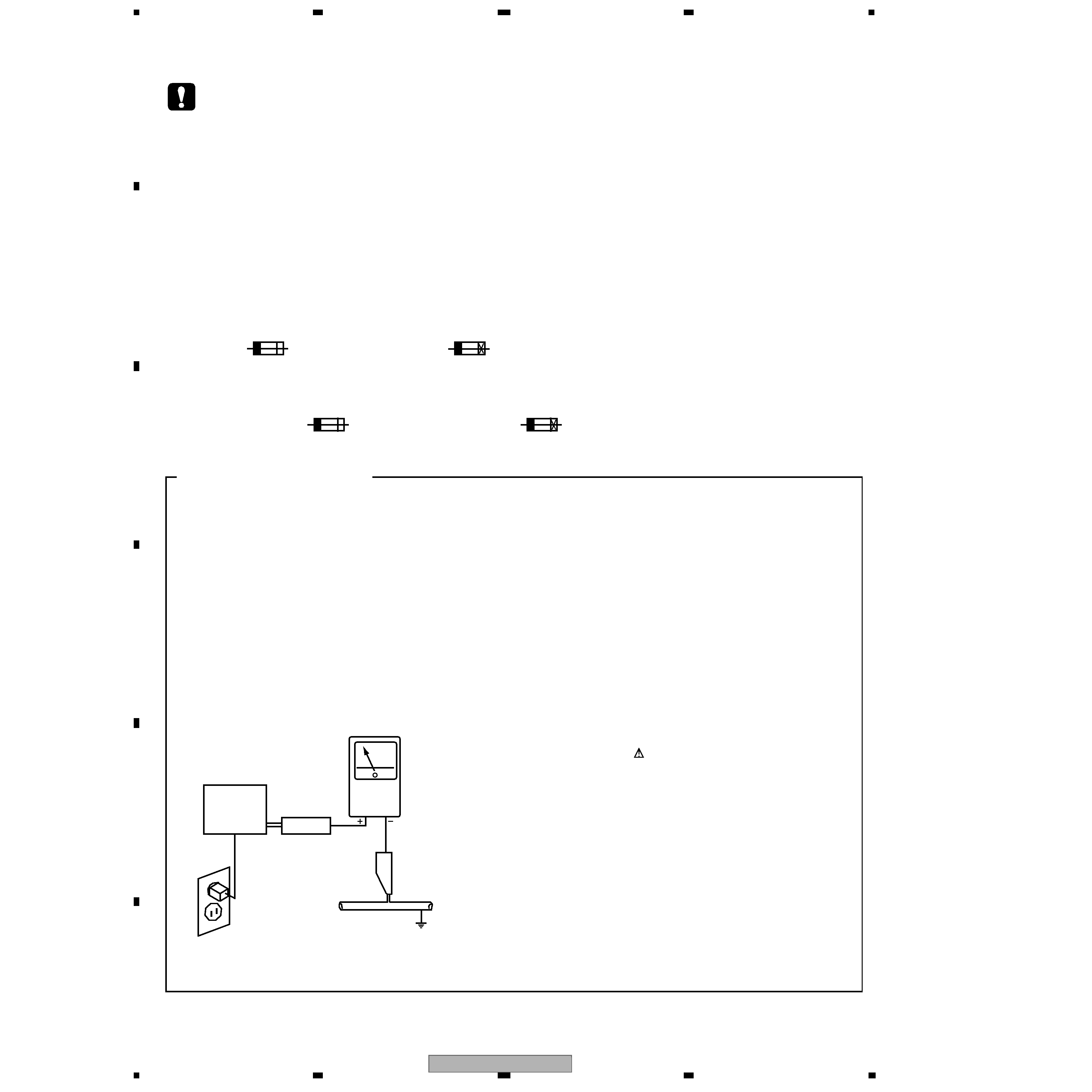
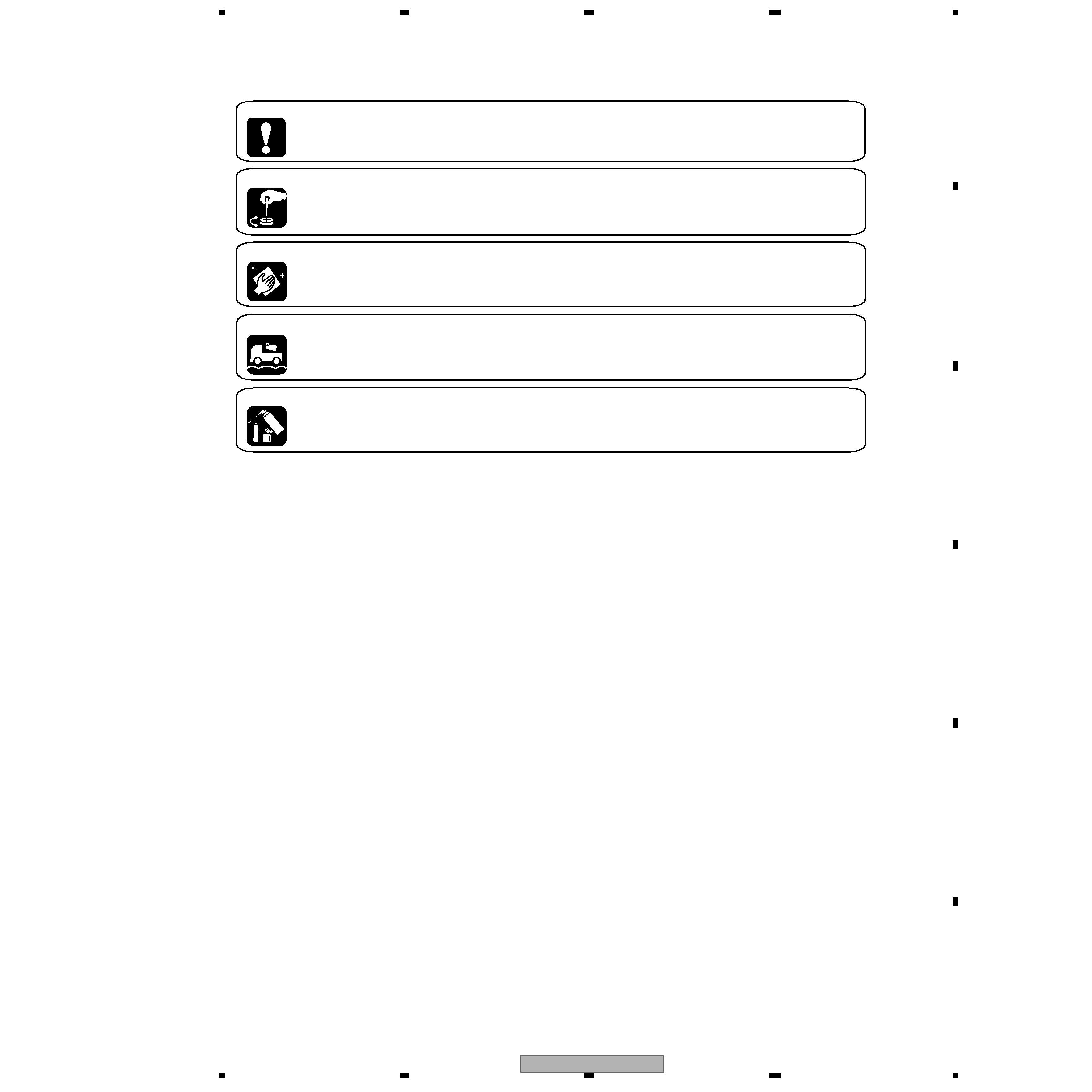
SAFETY INFORMATION ..................................................................................................................................... 2
1. SPECIFICATIONS ............................................................................................................................................ 6
2. EXPLODED VIEWS AND PARTS LIST ............................................................................................................ 8
2.1 PACKING ................................................................................................................................................... 8
2.2 EXTERIOR SECTION.............................................................................................................................. 10
2.3 CHASSIS SECTION ................................................................................................................................ 12
2.4 REAR PANEL SECTION.......................................................................................................................... 14
2.5 HEAT SINK SECTION.............................................................................................................................. 16
2.6 FRONT PANEL SECTION ....................................................................................................................... 18
3. BLOCK DIAGRAM AND SCHEMATIC DIAGRAM ..........................................................................................20
3.1 BLOCK DIAGRAM ................................................................................................................................... 20
3.2 OVERALL WIRING DIAGRAM................................................................................................................. 32
3.3 FM/AM TUNER MODULE ........................................................................................................................ 34
3.4 A/V I/O ASSY ........................................................................................................................................... 36
3.5 COMPOSITE ASSY ................................................................................................................................. 38
3.6 S-VIDEO ASSY........................................................................................................................................ 40
3.7 V-CONVERT ASSY .................................................................................................................................. 42
3.8 COMPONENT ASSY ............................................................................................................................... 44
3.9 VIDEO CON., MIC AMP, MIC & OPT, FRONT A/V and H.P. ASSYS ....................................................... 46
3.10 ANALOG IN & A/D ASSY(1/3) ............................................................................................................... 48
3.11 ANALOG IN & A/D ASSY(2/3) ............................................................................................................... 50
3.12 ANALOG IN & A/D ASSY(3/3) ............................................................................................................... 52
3.13 DISPLAY, INPUT SEL, MULTI JOG and VOL ASSYS ........................................................................... 54
3.14 VR & PRE OUT ASSY(1/3) .................................................................................................................... 56
3.15 VR & PRE OUT ASSY(2/3) .................................................................................................................... 58
3.16 VR & PRE OUT ASSY(3/3) .................................................................................................................... 60
3.17 MOTHER ASSY ..................................................................................................................................... 62
3.18 DSP ASSY(1/6)...................................................................................................................................... 64
3.19 DSP ASSY(2/6)...................................................................................................................................... 66
3.20 DSP ASSY(3/6)...................................................................................................................................... 68
3.21 DSP ASSY(4/6)...................................................................................................................................... 70
3.22 DSP ASSY(5/6)...................................................................................................................................... 72
3.23 DSP ASSY(6/6)...................................................................................................................................... 74
3.24 DSP3 ASSY ........................................................................................................................................... 76
3.25 DAC10 ASSY(1/2).................................................................................................................................. 78
3.26 DAC10 ASSY(2/2).................................................................................................................................. 80
3.27 POWER AMP(L) and POWER AMP(C) ASSYS .................................................................................... 82
3.28 POWER AMP(R), POWER AMP(BR) and POWER AMP(G) ASSYS.................................................... 84
3.29 LOCAL SUPPLY ASSY .......................................................................................................................... 86
3.30 AC PRIMARY, POWER SW, SP(A), FL SUPPLY and STANDBY ASSYS ............................................. 88
3.31 POSISTER (L) (R) (MT), DSP DIODE, SP (B), DIODE, FUSE, TARANS (A) (B) and 12V TRIGGER .. 90
3.32 1394 MODULE(1/2) ASSY..................................................................................................................... 92
3.33 1394 MODULE(2/2) ASSY..................................................................................................................... 94
4. PCB CONNECTION DIAGRAM ..................................................................................................................... 96
4.1 FM/AM TUNER MODULE ........................................................................................................................ 97
4.2 A/V I/O ASSY ........................................................................................................................................... 98
4.3 COMPOSITE ASSY ................................................................................................................................. 99
4.4 S-VIDEO ASSY...................................................................................................................................... 100
4.5 V-CONVERT ASSY ................................................................................................................................ 101
4.6 COMPONENT ASSY ............................................................................................................................. 102
4.7 VIDEO CONNECT ASSY....................................................................................................................... 103
4.8 MIC AMP, MIC, FRONT A/V and HEADPHONE ASSYS ....................................................................... 104
4.9 ANALOG IN & A/D ASSY ...................................................................................................................... 106
4.10 DISPLAY, INPUT SEL, MULTI JOG, FL SUP. and STANDBY ASSYS ................................................. 108
4.11 VR & PRE OUT ASSY ......................................................................................................................... 112
4.12 MOTHER and 12V TRIGGER ASSYS ................................................................................................. 114
4.13 DSP ASSY ........................................................................................................................................... 118
4.14 DAC10 ASSY ....................................................................................................................................... 120
4.15 DSP3 ASSY ......................................................................................................................................... 122
4.16 POWER AMP(L) and POSISTER(L) ASSYS....................................................................................... 123
4.17 POWER AMP(R) and POSISTER(R) ASSYS...................................................................................... 125
4.18 POWER AMP(C), POWER AMP(BR) and POWER AMP(G) ASSYS.................................................. 127
4.19 LOCAL SUPPLY and DSP DIODE ASSYS.......................................................................................... 128
4.20 AC PRIMARY, POWER SW, POSISTER(MT) and SP(A) ASSYS ....................................................... 130
4.21 TRANS(A), TRANS(B), DIODE and FUSE ASSYS ............................................................................. 132
background image
VSX-59TXi
5
5
678
56
7
8
C
D
F
A
B
E
4.22 SP(B) ASSY..........................................................................................................................................133
4.23 1394 MODULE ASSY...........................................................................................................................134
5. PCB PARTS LIST ..........................................................................................................................................135
6. ADJUSTMENT ..............................................................................................................................................149
7. GENERAL INFORMATION ...........................................................................................................................150
7.1 DIAGNOSIS ............................................................................................................................................150
7.1.1 Test mode .........................................................................................................................................150
7.1.2 FAILURE DIAGNOSIS OF THE POWER AMPLIFIER .....................................................................151
7.1.3 PROTECTION CIRCUIT CONTROL SPECIFICATIONS .................................................................152
7.1.4 1394 Unit ..........................................................................................................................................156
7.1.5 TROUBLE SHOOTING OF THE DSP ASSY....................................................................................158
7.1.6 OUTLINE OF THE WAVEFORMS RECEIVED BY THE DSP SECTION .........................................174
7.1.7 Disassembly .....................................................................................................................................180
7.2 PARTS ....................................................................................................................................................186
7.2.1 IC......................................................................................................................................................186
7.3 REMOTE CONTROL UNIT.....................................................................................................................193
7.3.1 EXPLODED VIEWS and PARTS LIST .............................................................................................193
7.3.2 Remote SCH ....................................................................................................................................194
7.3.3 Remote PCB Diagram......................................................................................................................198
8. PANEL FACILITIES .......................................................................................................................................200
8.1 PANEL FACILITIES ..............................................................................................................................200
8.2 Remote Control ....................................................................................................................................203
8.3 Rear Panel ...........................................................................................................................................206

Reviews

There are no reviews of this manual yet.