PIONEER VSX-917V-K/SPWXJ Service Manual

Cover page of PIONEER VSX-917V-K/SPWXJ Service Manual

Service Manual for PIONEER VSX-917V-K/SPWXJ, downloadable as a PDF file.

We also have owner's manual to this model.

Manual details

  • Immediate download after payment.
  • Delivered as a PDF file.
  • The manual has 136 pages
  • File size: 9.93 MB
  • Available language versions: English
  • Different language versions may vary sligthly in file size and page count.

We guarantee that...

  • our manuals are complete,
  • the manual includes circuit diagrams,
  • our manuals are checked with antivirus,
  • We'll issue refund if the manual is damaged, incomplete or unreadable (our refund policy)

Sample pages

Thumbnail of page 1Thumbnail of page 2Thumbnail of page 3Thumbnail of page 4
Thumbnail of page 5Thumbnail of page 6Thumbnail of page 7Thumbnail of page 8
Thumbnail of page 9
background image
ORDER NO.
PIONEER CORPORATION 4-1, Meguro 1-chome, Meguro-ku, Tokyo 153-8654, Japan
PIONEER ELECTRONICS (USA) INC. P.O. Box 1760, Long Beach, CA 90801-1760, U.S.A.
PIONEER EUROPE NV Haven 1087, Keetberglaan 1, 9120 Melsele, Belgium
PIONEER ELECTRONICS ASIACENTRE PTE. LTD. 253 Alexandra Road, #04-01, Singapore 159936
PIONEER CORPORATION 2007
UP
DOWN
MULTI JOG
MASTER
VOLUME
ENTER
VSX-917V
STANDBY/ON
PHONES
DVD/LD
TV/SAT
DVR / VCR
VIDEO/FRONT AUDIO
CD
CD-R/TAPE/MD
USB
FM
MIDNIGHT/
LOUDNESS
SIGNAL
SELECT
SOUND
RETRIEVER
ACOUSTIC
EQ
PHASE
CONTROL
AUTO SURR/
DIRECT
TUNING/
STATION
SETUP
RETURN
TONE
TUNER
EDIT
PTY
SEARCH
SPEAKERS
MULTI JOG
STANDARD
ADVANCED
SURROUND
STEREO/
F.S.SURR
LISTENING MODE
AM
AUX
PHASE
CONTROL
MCACC/
AUDIO IN
AUDIO
R
L
VIDEO
DIGITAL IN
VIDEO INPUT
DIGITAL PRECISION
PROCESSING
USB
VSX-917V-K
RRV3559
AUDIO/VIDEO MULTI-CHANNEL RECEIVER
VSX-917V-K
VSX-917V-S
VSX-817-K
VSX-817-S
THIS MANUAL IS APPLICABLE TO THE FOLLOWING MODEL(S) AND TYPE(S).
Model
Type
Power Requirement
Remarks
VSX-917V-K
MYXJ5
AC 220 V to 230 V
VSX-917V-S
MYXJ5
AC 220 V to 230 V
VSX-817-K
MYXJ5
AC 220 V to 230 V
VSX-817-S
MYXJ5
AC 220 V to 230 V
For details, refer to "Important Check Points for Good Servicing".
T-ZZK MAR. 2007 printed in Japan
background image
VSX-917V-K
2
12
34
12
3
4
C
D
F
A
B
E
SAFETY INFORMATION
This service manual is intended for qualified service technicians; it is not meant for the casual
do-it-yourselfer. Qualified technicians have the necessary test equipment and tools, and have been
trained to properly and safely repair complex products such as those covered by this manual.
Improperly performed repairs can adversely affect the safety and reliability of the product and may
void the warranty. If you are not qualified to perform the repair of this product properly and safely, you
should not risk trying to do so and refer the repair to a qualified service technician.
WARNING
This product contains lead in solder and cer tain electrical par ts contain chemicals which are known to the state of California to
cause cancer, bir th defects or other reproductive harm.
Health & Safety Code Section 25249.6 ­ Proposition 65
NOTICE
(FOR CANADIAN MODEL ONLY)
Fuse symbols
(fast operating fuse)
and/or
(slow operating fuse) on PCB indicate that replacement
parts must be of identical designation.
REMARQUE
(POUR MODÈLE CANADIEN SEULEMENT)
Les symboles de fusible
(fusible de type rapide)
et/ou
(fusible de type lent) sur CCI indiquent que
les pièces de remplacement doivent avoir la même désignation.
ANY MEASUREMENTS NOT WITHIN THE
LIMITS OUTLINED ABOVE ARE INDICATIVE
OF A POTENTIAL SHOCK HAZARD AND
MUST BE CORRECTED BEFORE RETURN-
ING THE APPLIANCE TO THE CUSTOMER.
2. PRODUCT SAFETY NOTICE
Many electrical and mechanical parts in the appliance
have special safety related character istics. These are
often not evident
from visual
inspection nor the
protection afforded by them necessarily can be obtained
by using replacement components rated for voltage,
wattage, etc. Replacement par ts which have these
special safety character istics are identified in this
Service Manual.
Electr ical components having such features are
identified by marking with a
on the schematics and
on the parts list in this Service Manual.
The use of a substitute replacement component which
does not have the same safety characteristics as the
PIONEER recommended replacement one, shown in the
parts list in this Service Manual, may create shock, fire,
or other hazards.
Product Safety is continuously under review and new
instructions are issued from time to time. For the latest
infor mation, always consult the current PIONEER
Service Manual. A subscription to, or
additional copies
of, PIONEER Ser vice Manual may be obtained at a
nominal charge from PIONEER.
(FOR USA MODEL ONLY)
1. SAFETY PRECAUTIONS
The following check should be perfor med for the
continued protection of the customer and ser vice
technician.
LEAKAGE CURRENT CHECK
Measure leakage current to a known ear th ground
(water pipe, conduit, etc.) by connecting a leakage
current tester such as Simpson Model 229-2 or
equivalent between the ear th ground and all exposed
metal par ts of the appliance (input/output ter minals,
screwheads, metal overlays, control shaft, etc.). Plug
the AC line cord of the appliance directly into a 120V
AC 60 Hz outlet and turn the AC power switch on. Any
current measured must not exceed 0.5 mA.
Device
under
test
Leakage
current
tester
Earth
ground
Reading should
not be above
0.5 mA
Also test with
plug reversed
(Using AC adapter
plug as required)
Test all
exposed metal
surfaces
AC Leakage Test
background image
VSX-917V-K
3
56
78
56
7
8
C
D
F
A
B
E
[Important Check Points for Good Servicing]
In this manual, procedures that must be performed during repairs are marked with the below symbol.
Please be sure to confirm and follow these procedures.
1. Product safety
Please conform to product regulations (such as safety and radiation regulations), and maintain a safe servicing environment by
following the safety instructions described in this manual.
1 Use specified parts for repair.
Use genuine parts. Be sure to use important parts for safety.
2 Do not perform modifications without proper instructions.
Please follow the specified safety methods when modification(addition/change of parts) is required due to interferences such as
radio/TV interference and foreign noise.
3 Make sure the soldering of repaired locations is properly performed.
When you solder while repairing, please be sure that there are no cold solder and other debris.
Soldering should be finished with the proper quantity. (Refer to the example)
4 Make sure the screws are tightly fastened.
Please be sure that all screws are fastened, and that there are no loose screws.
5 Make sure each connectors are correctly inserted.
Please be sure that all connectors are inserted, and that there are no imperfect insertion.
6 Make sure the wiring cables are set to their original state.
Please replace the wiring and cables to the original state after repairs.
In addition, be sure that there are no pinched wires, etc.
7 Make sure screws and soldering scraps do not remain inside the product.
Please check that neither solder debris nor screws remain inside the product.
8 There should be no semi-broken wires, scratches, melting, etc. on the coating of the power cord.
Damaged power cords may lead to fire accidents, so please be sure that there are no damages.
If you find a damaged power cord, please exchange it with a suitable one.
9 There should be no spark traces or similar marks on the power plug.
When spark traces or similar marks are found on the power supply plug, please check the connection and advise on secure
connections and suitable usage. Please exchange the power cord if necessary.
0 Safe environment should be secured during servicing.
When you perform repairs, please pay attention to static electricity, furniture, household articles, etc. in order to prevent injuries.
Please pay attention to your surroundings and repair safely.
2. Adjustments
To keep the original performance of the products, optimum adjustments and confirmation of characteristics within specification.
Adjustments should be performed in accordance with the procedures/instructions described in this manual.
4. Cleaning
For parts that require cleaning, such as optical pickups, tape deck heads, lenses and mirrors used in projection monitors, proper
cleaning should be performed to restore their performances.
3. Lubricants, Glues, and Replacement parts
Use grease and adhesives that are equal to the specified substance.
Make sure the proper amount is applied.
5. Shipping mode and Shipping screws
To protect products from damages or failures during transit, the shipping mode should be set or the shipping screws should be
installed before shipment. Please be sure to follow this method especially if it is specified in this manual.
background image
VSX-917V-K
4
12
34
12
3
4
C
D
F
A
B
E
CONTENTS
SAFETY INFORMATION ..................................................................................................................................... 2
1. SPECIFICATIONS ............................................................................................................................................ 5
2. EXPLODED VIEWS AND PARTS LIST ............................................................................................................ 6
2.1 PACKING SECTION .................................................................................................................................. 6
2.2 EXTERIOR SECTION................................................................................................................................ 8
2.3 FRONT PANEL SECTION ....................................................................................................................... 12
3. BLOCK DIAGRAM AND SCHEMATIC DIAGRAM ..........................................................................................14
3.1 BLOCK DIAGRAM ................................................................................................................................... 14
3.2 OVERALL WIRING CONNECTION DIAGRAM........................................................................................ 16
3.3 MAIN ASSY (1/3) ..................................................................................................................................... 18
3.4 MAIN ASSY (2/3) ..................................................................................................................................... 20
3.5 MAIN ASSY (3/3) ..................................................................................................................................... 22
3.6 DSP ASSY (1/2)....................................................................................................................................... 24
3.7 DSP ASSY (2/2)....................................................................................................................................... 26
3.8 POWER PACK (1/2), TRANS2 and TRANS3 ASSYS .............................................................................. 28
3.9 POWER PACK ASSY (2/2) ...................................................................................................................... 30
3.10 COMPONENT VIDEO, HEAD PHONE and 5.1CH INPUT ASSYS ....................................................... 32
3.11 FRONT DISPLAY, ROTARY ENCODER and POWER KEY ASSYS...................................................... 34
3.12 S.VIDEO, TRANS4 and REGULATOR ASSYS ...................................................................................... 36
3.13 COMP VIDEO and BOARD TO BOARD ASSYS ................................................................................... 38
3.14 VIDEO, DIGITAL INPUT, FRONT VIDEO and PRIMARY ASSYS.......................................................... 40
3.15 FRONT IN ASSY.................................................................................................................................... 42
3.16 HDMI & DVC ASSY (VSX-917V ONLY) ................................................................................................. 44
3.17 USB ASSY ............................................................................................................................................. 46
4. PCB CONNECTION DIAGRAM ..................................................................................................................... 48
4.1 USB ASSY ............................................................................................................................................... 49
4.2 MAIN ASSY ............................................................................................................................................. 50
4.3 DSP ASSY ............................................................................................................................................... 54
4.4 TRANS2 and TRANS3 ASSYS ................................................................................................................ 55
4.5 POWER PACK ASSY............................................................................................................................... 56
4.6 COMPONENT VIDEO ASSY ................................................................................................................... 60
4.7 HEADPHONE and 5.1CH INPUT ASSYS ............................................................................................... 61
4.8 FRONT DISPLAY ASSY .......................................................................................................................... 62
4.9 ROTARY ENCODER and POWER KEY ASSYS ..................................................................................... 66
4.10 S.VIDEO ASSY ...................................................................................................................................... 68
4.11 TRANS4 and REGULATOR ASSYS ...................................................................................................... 69
4.12 COMP VIDEO and BOARD TO BOARD ASSYS (VSX-917V ONLY)..................................................... 70
4.13 VIDEO ASSY (VSX-817 ONLY) ............................................................................................................. 72
4.14 DIGITAL INPUT and FRONT VIDEO ASSYS ........................................................................................73
4.15 PRIMARY ASSY .................................................................................................................................... 74
4.16 FRONT IN ASSY.................................................................................................................................... 76
4.17 HDMI&DVC ASSY (VSX-917V ONLY) ................................................................................................... 77
5. PCB PARTS LIST ........................................................................................................................................... 78
6. ADJUSTMENT ............................................................................................................................................... 99
7. GENERAL INFORMATION ........................................................................................................................... 100
7.1 DIAGNOSIS ........................................................................................................................................... 100
7.1.1 DSP TROUBLESHOOTING ............................................................................................................ 100
7.1.2 HDMI TROUBLESHOOTING (VSX-917V ONLY) ............................................................................ 108
7.1.3 DISASSEMBLY................................................................................................................................ 116
7.2 PARTS.................................................................................................................................................... 120
7.2.1 IC ..................................................................................................................................................... 120
7.3 EXPLANATION ...................................................................................................................................... 125
7.3.1 DETECTION CIRCUIT .................................................................................................................... 125
7.3.2 AMPLIFIER SYSTEM PROTECTION OPERATION SPECIFICATION............................................ 127
7.3.3 AMPLIFIER FAILURE DIAGNOSIS FLOW CHART ........................................................................ 129
8. PANEL FACILITIES ...................................................................................................................................... 130
background image
VSX-917V-K
5
56
78
56
7
8
C
D
F
A
B
E
1. SPECIFICATIONS
Amplifier section
VSX-917V
·
Continuous power output (stereo)
Front . . . . . . . . . . . . . . . . . . . . . . . 100 W + 100 W
(DIN 1 kHz, THD 1.0 %, 8
)
·
Rated power output
(surround / 20 Hz to 20 kHz, THD 0.08 %, 8 W )
Front . . . . . . . . . . . . . . . . . . . . . 90 W per channel
Center . . . . . . . . . . . . . . . . . . . . . . . . . . . . . . 90 W
Surround . . . . . . . . . . . . . . . . . . 90 W per channel
Surround Back. . . . . . . . . . . . . . 90 W per channel
·
Rated power output
(surround / 1 kHz, THD 1 %, 8
)
Front . . . . . . . . . . . . . . . . . . . . 110 W per channel
Center . . . . . . . . . . . . . . . . . . . . . . . . . . . . . 110 W
Surround . . . . . . . . . . . . . . . . . 110 W per channel
Surround Back. . . . . . . . . . . . . 110 W per channel
Audio section
·
Input (Sensitivity/Impedance)
CD, DVR/VCR, CD-R/TAPE/MD,
DVD/LD, TV/SAT . . . . . . . . . . . . . . 200 mV/47 k
·
Frequency response
CD, DVR/VCR, CD-R/TAPE/MD, DVD/LD,
TV/SAT . . . . . . . . . . . . . 5 Hz to 100 000 Hz
dB
·
Output (Level/Impedance)
DVR/VCR REC, CD-R/TAPE/
MD REC. . . . . . . . . . . . . . . . . . . . . 200 mV/2.2 k
·
Tone control
Bass. . . . . . . . . . . . . . . . . . . . . . . .
±6 dB (100 Hz)
Treble. . . . . . . . . . . . . . . . . . . . . . .
±6 dB (10 kHz)
Loudness. . . . . . . . +10 dB/+5 dB (100 Hz/10 kHz)
(at volume level -50 dB)
·
Signal-to-Noise Ratio DIN (Continuous
rated power output / 50 mW)
CD, DVR/VCR, CD-R/TAPE/MD,
DVD/LD, TV/SAT . . . . . . . . . . . . . . . . 88 dB/64 dB
Video Section
·
Input (Sensitivity/Impedance)
DVR/VCR, DVD/LD, TV/SAT . . . . . . . 1 Vp-p/75
·
Output (Level/Impedance)
DVR/VCR, MONITOR OUT . . . . . . . . 1 Vp-p/75
FM Tuner Section
Frequency Range . . . . . . . . 87.5 MHz to 108 MHz
Usable Sensitivity . . . . . . . . . . Mono:13.2 dBf, IHF
(1.3
µV/ 75 )
50 dB Quieting Sensitivity. . . . . . . . Mono: 20.2 dB
Stereo: 38.6 dBf
Signal-to-Noise Ratio. . . . Mono: 73 dB (at 85 dBf)
Stereo: 70 dB (at 85 dBf)
Distortion . . . . . . . . . . . . . . . Stereo: 0.5 % (1 kHz)
Alternate Channel Selectivity . . . . 60 dB (400 kHz)
Stereo Separation. . . . . . . . . . . . . . . 40 dB (1 kHz)
Frequency Response . . . . . . . . . . 30 Hz to 15 kHz
(
±1 dB)
Antenna Input (DIN) . . . . . . . . . . 75
unbalanced
AM Tuner Section
Frequency Range. . . . . . . . . 531 kHz to 1602 kHz
Sensitivity (IHF, Loop antenna). . . . . . . . 350
µV/m
Signal-to-Noise Ratio . . . . . . . . . . . . . . . . . . 50 dB
Antenna . . . . . . . . . . . . . . . . . . . . . . Loop antenna
Miscellaneous
Power requirements
. . . . . . . . . . . . . . AC 220 V to 230 V, 50 Hz/60 Hz
Power consumption. . . . . . . . . . . . . . . . . . . 395 W
In standby. . . . . . . . . . . . . . . . . . . . . . . . . 0.5 W
Dimensions
. . . . . . 420 (W) mm x 158 (H) mm x 352.5 (D) mm
Weight (without package). . . . . 8.8 kg (VSX-917V)
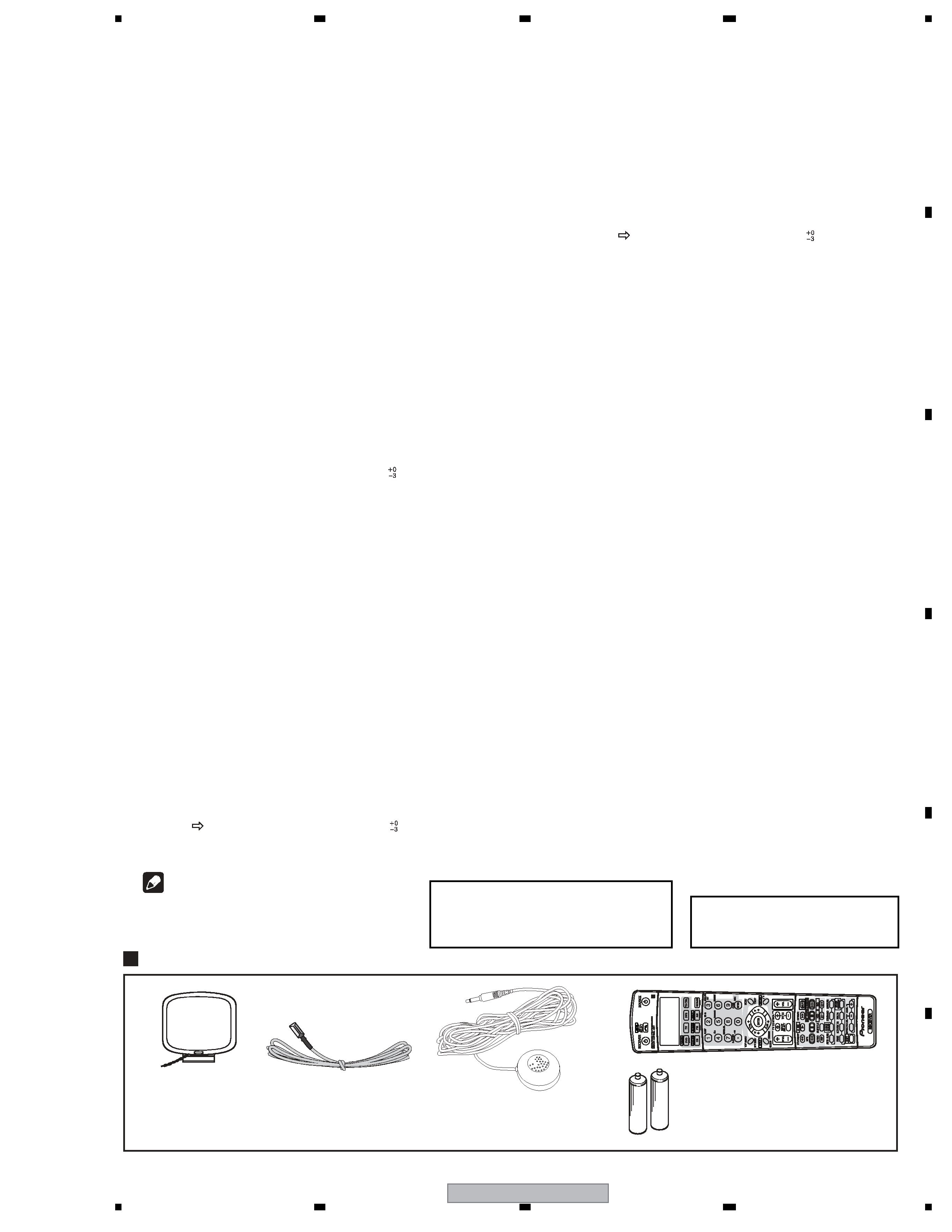
Furnished Parts
Microphone (for Auto MCACC setup). . . . . . . . . . 1
Dry cell batteries (AA size IEC R6) . . . . . . . . . . . 2
Remote control . . . . . . . . . . . . . . . . . . . . . . . . . . 1
AM loop antenna . . . . . . . . . . . . . . . . . . . . . . . . . 1
FM wire antenna . . . . . . . . . . . . . . . . . . . . . . . . . 1
Warranty card . . . . . . . . . . . . . . . . . . . . . . . . . . . 1
Operating instructions
Note
· Specifications and the design are subject
to possible modifications without notice,
due to improvements.
·
Frequency response
DVR/VCR, DVD/LD,
TV/SAT
MONITOR . . . . . 5 Hz to 7 MHz
dB
Signal-to-Noise Ratio . . . . . . . . . . . . . . . . . . 55 dB
Crosstalk. . . . . . . . . . . . . . . . . . . . . . . . . . . . 50 dB
Component video section
·
Input (Sensitivity/Impedance)
DVD/LD, TV/SAT, DVR/VCR. . . . . . . 1 Vp-p/75
·
Output (Level/Impedance)
MONITOR OUT . . . . . . . . . . . . . . . . . 1 Vp-p/75
·
Frequency response
DVD/LD, TV/SAT,
DVR/VCR
MONITOR. . . 5 Hz to 40 MHz
dB
Signal-to-Noise Ratio . . . . . . . . . . . . . . . . . . 60 dB
Manufactured under license from Dolby
Laboratories. "Dolby", "Pro Logic",
"Surround EX", and the double-D symbol
are trademarks of Dolby Laboratories.
"DTS" and "DTS-ES | Neo:6" are
registered trademarks of DTS, Inc.
"96/24" is a trademark of DTS, Inc.
Weight (without package). . . . . . 8.5 kg (VSX-817)
Accessories
Remote control
(VSX-917V : XXD3128)
(VSX-817 : XXD3133)
AM loop antenna
(ATB7013)
FM wire antenna
(ADH7030)
AA size IEC R6
Dry cell batteries (x2)
Microphone
(for Auto MCACC setup)
(APM7008)

Reviews

There are no reviews of this manual yet.