PIONEER SVM-1000/KUCXJ Service Manual

Cover page of PIONEER SVM-1000/KUCXJ Service Manual

Service Manual for PIONEER SVM-1000/KUCXJ, downloadable as a PDF file.

We also have owner's manual to this model.

Manual details

  • Immediate download after payment.
  • Delivered as a PDF file.
  • The manual has 240 pages
  • File size: 32.35 MB
  • Available language versions: English
  • Different language versions may vary sligthly in file size and page count.

We guarantee that...

  • our manuals are complete,
  • the manual includes circuit diagrams,
  • our manuals are checked with antivirus,
  • We'll issue refund if the manual is damaged, incomplete or unreadable (our refund policy)

Sample pages

Thumbnail of page 1Thumbnail of page 2Thumbnail of page 3Thumbnail of page 4
Thumbnail of page 5Thumbnail of page 6Thumbnail of page 7Thumbnail of page 8
Thumbnail of page 9
background image
ORDER NO.
PIONEER CORPORATION 4-1, Meguro 1-chome, Meguro-ku, Tokyo 153-8654, Japan
PIONEER ELECTRONICS (USA) INC. P.O. Box 1760, Long Beach, CA 90801-1760, U.S.A.
PIONEER EUROPE NV Haven 1087, Keetberglaan 1, 9120 Melsele, Belgium
PIONEER ELECTRONICS ASIACENTRE PTE. LTD. 253 Alexandra Road, #04-01, Singapore 159936
PIONEER CORPORATION 2007
2007 Printed in Japan
MIC
FADER START
HEAD PHONES
VIDEO INPUT
USB
DVD
CH 1
VIDEO
EX
CH 4
MIC
OFF
ON
TALK
OVER
MIN
DVD/LINE
PHONO
MAX
VIDEO
VIDEO
S-VIDEO
EX
VIDEO TRIM
MIC 1
MIC1
LEVEL
MIC2
LEVEL
HI
LOW
CH1
AUDIO INPUT
AUDIO TRIM
dB
OVER
10
7
4
2
1
0
­1
­2
­3
­5
­7
­10
­15
­24
+9
MID
+6
-26
HI
+6
-26
LOW
CUE
CROSS FADER
ASSIGN
PROFESSIONAL SOUND&VISION MIXER
B
A
SVM-1000
+6
-26
10
9
8
7
6
5
4
3
2
1
0
A THRU B
1
VIDEO INPUT
DVD
MIN
DVD
LINE
DIGITAL
MAX
VIDEO
S-VIDEO
VIDEO TRIM
AUDIO INPUT
AUDIO TRIM
dB
OVER
10
7
4
2
1
0
­1
­2
­3
­5
­7
­10
­15
­24
+9
MID
+6
-26
HI
+6
-26
LOW
CUE
CROSS FADER
ASSIGN
+6
-26
10
9
8
7
6
5
4
3
2
1
0
A THRU B
2
VIDEO INPUT
DVD
MIN
DVD
LINE
DIGITAL
MAX
VIDEO
S-VIDEO
VIDEO TRIM
AUDIO INPUT
CH SELECT
AUDIO TRIM
dB
OVER
10
7
4
2
1
0
­1
­2
­3
­5
­7
­10
­15
­24
+9
MID
+6
-26
HI
+6
-26
LOW
CUE
CROSS FADER
ASSIGN
+6
-26
10
9
8
7
6
5
4
3
2
1
0
CROSS FADER CURVE
SD CARD
A THRU B
3
dB
OVER
10
7
4
2
1
0
­1
­2
­3
­5
­7
­10
­15
­24
VIDEO INPUT
DVD
MIN
LINE
PHONO
MAX
VIDEO
VIDEO
S-VIDEO
VIDEO TRIM
AUDIO INPUT
AUDIO TRIM
dB
LR
OVER
10
7
4
2
1
0
­1
­2
­3
­5
­7
­10
­15
­24
+9
BOOTH MONITOR
0
MID
+6
-26
HI
+6
-26
LOW
CUE
CROSS FADER
ASSIGN
+6
-26
BALANCE
MASTER
R
L
CUE
10
9
8
7
6
5
4
3
2
1
0
CH FADER CURVE
VIDEO
MASTER LEVEL
WHITE
BLACK
MONO STEREO
A THRU B
4
EX
0
0
0
+12
-12
+12
-12
CH2
CH3
CH4
MONO SPLIT
STEREO
MIXING
PHONES
MASTER
CUE
LEVEL
AUDIO MASTER LEVEL
0
TIME/
PARAMETER
LEVEL/
DEPTH
EFFECT
CUE
VIDEO FX
PATTERN/
TEXT BANK
MAX
MIN
FADER
AV SYNC
VIDEO
SOLO MODE
JPEG
VIEWER
ON/OFF
SET UP
VIDEO EQ
MASTER
MONITOR
SET UP
UTILITY
EFFECT
ON/OFF
2
4
5
6
7
SVM-1000
RRV3678
SOUND & VISION MIXER
SVM-1000
THIS MANUAL IS APPLICABLE TO THE FOLLOWING MODEL(S) AND TYPE(S).
Model
Type
Power Requirement
Remarks
SVM-1000
KUCXJ
AC 120 V
SVM-1000
WYXJ5
AC 220 V to 240 V
SVM-1000
TLXJ
AC 110 V to 240 V
For details, refer to "Important Check Points for good servicing".
T-ZZR DEC.
background image
2
SVM-1000
1
2
3
4
A
B
C
D
E
F
1
2
3
4
SAFETY INFORMATION
1. SAFETY PRECAUTIONS
The following check should be performed for the
continued protection of the customer and service
technician.
LEAKAGE CURRENT CHECK
Measure leakage current to a known earth ground
(water pipe, conduit, etc.) by connecting a leakage
current tester such as Simpson Model 229-2 or
equivalent between the earth ground and all exposed
metal parts of the appliance (input/output terminals,
screwheads, metal overlays, control shaft, etc.). Plug
the AC line cord of the appliance directly into a 120V
AC 60 Hz outlet and turn the AC power switch on. Any
current measured must not exceed 0.5 mA.
ANY
MEASUREMENTS
NOT WITHIN THE
LIMITS
OUTLINED ABOVE ARE INDICATIVE OF A POTENTIAL
SHOCK HAZARD AND MUST BE CORRECTED BEFORE
RETURNING THE APPLIANCE TO THE CUSTOMER.
2. PRODUCT SAFETY NOTICE
Many electrical and mechanical parts in the appliance
have special safety related characteristics. These are
often not evident from visual inspection nor the protection
afforded by them necessarily can be obtained by using
replacement components rated for voltage, wattage, etc.
Replacement parts which have these special safety
characteristics are identified in this Service Manual.
Electrical components having such features are
identified by marking with a > on the schematics and on
the parts list in this Service Manual.
The use of a substitute replacement component which
does not have the same safety characteristics as the
PIONEER recommended replacement one, shown in the
parts list in this Service Manual, may create shock, fire,
or other hazards.
Product Safety is continuously under review and new
instructions are issued from time to time. For the latest
information, always consult the current PIONEER Service
Manual. A subscription to, or additional copies of,
PIONEER Service Manual may be obtained at a nominal
charge from PIONEER.
Leakage
current
tester
Reading should
not be above
0.5 mA
Device
under
test
Test all
exposed metal
surfaces
Also test with
plug reversed
(Using AC adapter
plug as required)
Earth
ground
AC Leakage Test
(FOR USA MODEL ONLY)
WARNING
This product contains lead in solder and certain electrical parts contain chemicals which are known to the state of California to
cause cancer, birth defects or other reproductive harm.
Health & Safety Code Section 25249.6 - Proposition 65
NOTICE
(FOR CANADIAN MODEL ONLY)
Fuse symbols
(fast operating fuse) and/or
(slow operating fuse) on PCB indicate that replacement parts must
be of identical designation.
REMARQUE
(POUR MODÈLE CANADIEN SEULEMENT)
Les symboles de fusible
(fusible de type rapide) et/ou
(fusible de type lent) sur CCI indiquent que les pièces
de remplacement doivent avoir la même désignation.
This service manual is intended for qualified service technicians ; it is not meant for the casual
do-it-yourselfer. Qualified technicians have the necessary test equipment and tools, and have been
trained to properly and safely repair complex products such as those covered by this manual.
Improperly performed repairs can adversely affect the safety and reliability of the product and may
void the warranty. If you are not qualified to perform the repair of this product properly and safely, you
should not risk trying to do so and refer the repair to a qualified service technician.
background image
3
SVM-1000
5
6
7
8
5
6
7
8
A
B
C
D
E
F
(FOR USA MODEL ONLY)
The backlighting lamp of LCD in this equipment contains mercury. Disposal of this material may be
regulated due to environmental considerations according to Local, State or Federal Laws. For disposal
or recycling information, please contact your local authorities or the Electronics Industries
Alliance: www.eiae.org
This product contains mercury. Disposal of this material may be regulated due to environmental considerations.
For disposal or recycling information, please contact your local authorities or the Electronics Industries
Alliance: www.eiae.org.
background image
4
SVM-1000
1
2
3
4
A
B
C
D
E
F
1
2
3
4
[Important Check Points for Good Servicing]
In this manual, procedures that must be performed during repairs are marked with the below symbol.
Please be sure to confirm and follow these procedures.
1. Product safety
Please conform to product regulations (such as safety and radiation regulations), and maintain a safe servicing environment by
following the safety instructions described in this manual.
1 Use specified parts for repair.
Use genuine parts. Be sure to use important parts for safety.
2 Do not perform modifications without proper instructions.
Please follow the specified safety methods when modification(addition/change of parts) is required due to interferences such as
radio/TV interference and foreign noise.
3 Make sure the soldering of repaired locations is properly performed.
When you solder while repairing, please be sure that there are no cold solder and other debris.
Soldering should be finished with the proper quantity. (Refer to the example)
4 Make sure the screws are tightly fastened.
Please be sure that all screws are fastened, and that there are no loose screws.
5 Make sure each connectors are correctly inserted.
Please be sure that all connectors are inserted, and that there are no imperfect insertion.
6 Make sure the wiring cables are set to their original state.
Please replace the wiring and cables to the original state after repairs.
In addition, be sure that there are no pinched wires, etc.
7 Make sure screws and soldering scraps do not remain inside the product.
Please check that neither solder debris nor screws remain inside the product.
8 There should be no semi-broken wires, scratches, melting, etc.on the coating of the power cord.
Damaged power cords may lead to fire accidents, so please be sure that there are no damages.
If you find a damaged power cord, please exchange it with a suitable one.
9 There should be no spark traces or similar marks on the power plug.
When spark traces or similar marks are found on the power supply plug, please check the connection and advise on secure
connections and suitable usage. Please exchange the power cord if necessary.
a Safe environment should be secured during servicing.
When you perform repairs, please pay attention to static electricity, furniture, household articles, etc. in order to prevent injuries.
Please pay attention to your surroundings and repair safely.
2. Adjustments
To keep the original performance of the products, optimum adjustments and confirmation of characteristics within specification.
Adjustments should be performed in accordance with the procedures/instructions described in this manual.
4. Cleaning
For parts that require cleaning, such as optical pickups, tape deck heads, lenses and mirrors used in projection monitors, proper
cleaning should be performed to restore their performances.
3. Lubricants, Glues, and Replacement parts
Use grease and adhesives that are equal to the specified substance.
Make sure the proper amount is applied.
5. Shipping mode and Shipping screws
To protect products from damages or failures during transit, the shipping mode should be set or the shipping screws should be
installed before shipment. Please be sure to follow this method especially if it is specified in this manual.
background image
5
SVM-1000
5
6
7
8
5
6
7
8
A
B
C
D
E
F
CONTENTS
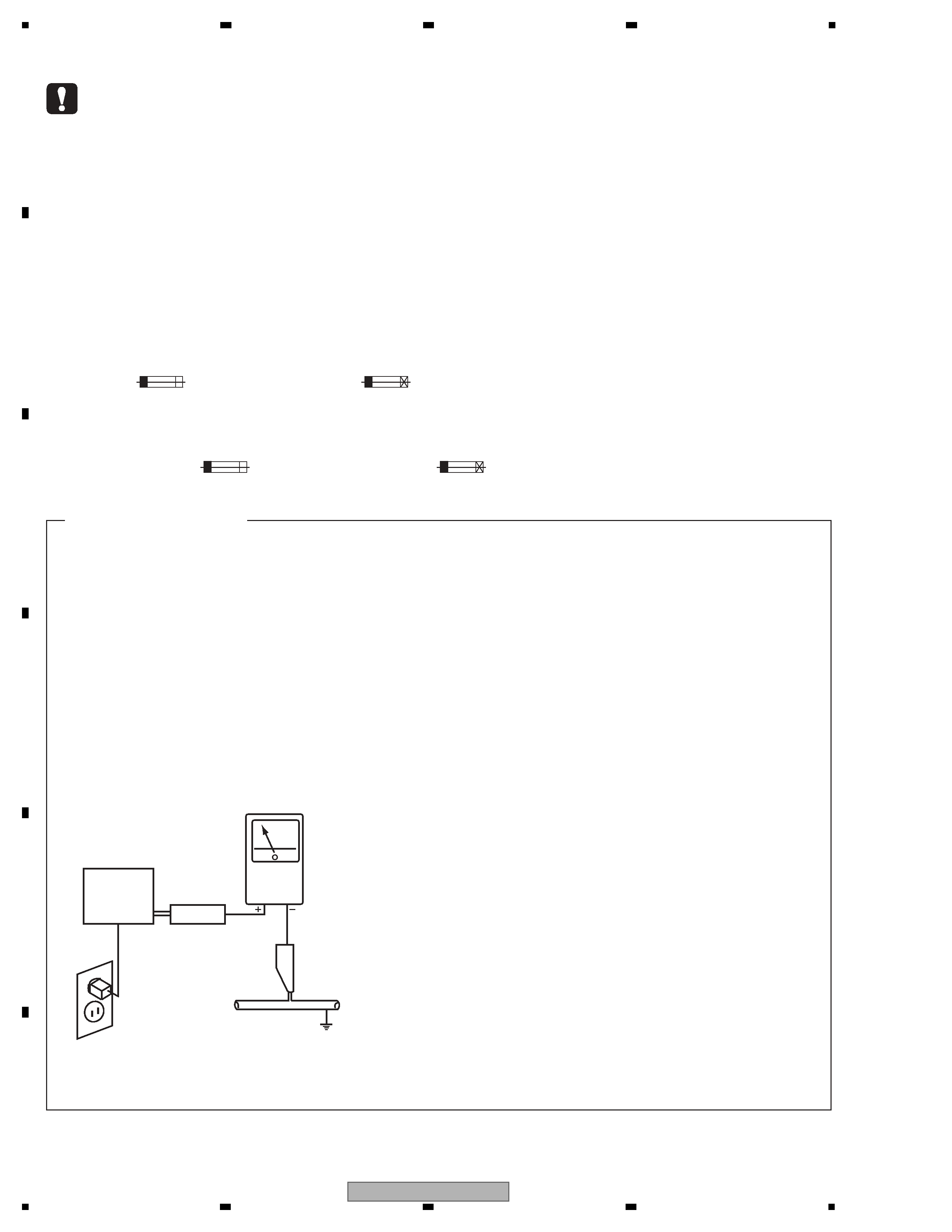
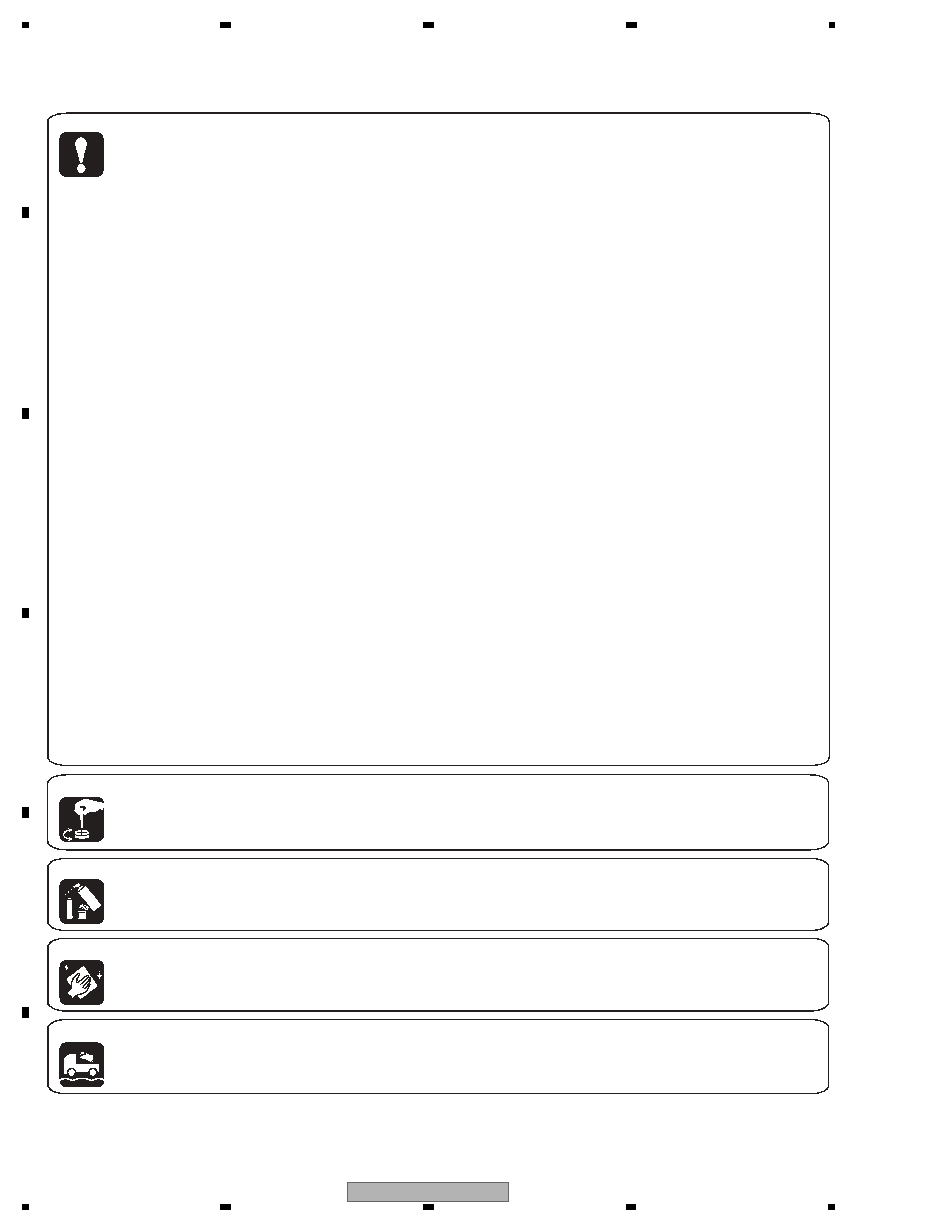
SAFETY INFORMATION......................................................................................................................................2
1. SERVICE PRECAUTIONS ................................................................................................................................7
1.1 NOTES ON SOLDERING ...........................................................................................................................7
2. SPECIFICATIONS.............................................................................................................................................7
2.1 ACCESSORIES ..........................................................................................................................................7
2.2 SPECIFICATIONS ......................................................................................................................................8
2.3 PANEL FACILITIES.....................................................................................................................................9
3. BASIC ITEMS FOR SERVICE ........................................................................................................................13
3.1 CHECK POINTS AFTER SERVICING .....................................................................................................13
3.2 PCB LOCATION .......................................................................................................................................14
4. BLOCK DIAGRAM ..........................................................................................................................................16
4.1 OVERALL WIRING DIAGRAM .................................................................................................................16
4.2 AUDIO BLOCK DIAGRAM........................................................................................................................18
4.3 VIDEO BLOCK DIAGRAM........................................................................................................................20
4.4 FUNCTION BLOCK DIAGRAM ................................................................................................................22
5. DIAGNOSIS ....................................................................................................................................................24
5.1 DIAGNOSIS FLOW...................................................................................................................................24
5.2 POWER ON SEQUENCE.........................................................................................................................25
6. SERVICE MODE .............................................................................................................................................27
6.1 LIST OF PAGES IN SERVICE MODE ......................................................................................................27
6.2 SERVICE MODE ......................................................................................................................................27
6.3 SERVICE MODE IDENTIFICATION .........................................................................................................28
6.4 LIST OF PAGES IN TEST MODO ............................................................................................................33
6.5 TEST MODE.............................................................................................................................................34
6.6 TEST MODE IDENTIFICATION................................................................................................................35
6.7 HOW TO USB DOWNLOAD .....................................................................................................................41
6.8 NOTES ON VARIOUS SETTINGS WHEN THE UNIT ARE REPLACED .................................................43
7. DISASSEMBLY ...............................................................................................................................................44
8. EACH SETTING AND ADJUSTMENT ............................................................................................................55
9. EXPLODED VIEWS AND PARTS LIST...........................................................................................................56
9.1 PACKING SECTION .................................................................................................................................56
9.2 EXTERIOR SECTION ..............................................................................................................................58
9.3 BOTTOM SECTION..................................................................................................................................60
9.4 OPERATION PANEL SECTION................................................................................................................62
9.5 LCD PANEL SECTION .............................................................................................................................64
10. SCHEMATIC DIAGRAM ................................................................................................................................66
10.1 AUD1 ASSY (1/5) ...................................................................................................................................66
10.2 AUD1 ASSY (2/5) ...................................................................................................................................68
10.3 AUD1 ASSY (3/5) ...................................................................................................................................70
10.4 AUD1 ASSY (4/5) ...................................................................................................................................72
10.5 AUD1 ASSY (5/5) ...................................................................................................................................74
10.6 AUD2 ASSY (1/5) ...................................................................................................................................76
10.7 AUD2 ASSY (2/5) ...................................................................................................................................78
10.8 AUD2 ASSY (3/5) ...................................................................................................................................80
10.9 AUD2 ASSY (4/5) ...................................................................................................................................82
10.10 AUD2 ASSY (5/5) .................................................................................................................................84
10.11 VIO1 ASSY ...........................................................................................................................................86
10.12 MJCK, VIN3 and VIO2 ASSYS.............................................................................................................88
10.13 MAIN ASSY (1/9)..................................................................................................................................90
10.14 MAIN ASSY (2/9)..................................................................................................................................94
10.15 MAIN ASSY (3/9)..................................................................................................................................98
10.16 MAIN ASSY (4/9)................................................................................................................................102
10.17 MAIN ASSY (5/9)................................................................................................................................106
10.18 MAIN ASSY (6/9)................................................................................................................................110
10.19 MAIN ASSY (7/9)................................................................................................................................114
10.20 MAIN ASSY (8/9)................................................................................................................................118
10.21 MAIN ASSY (9/9)................................................................................................................................122
10.22 SCPU ASSY (1/2)...............................................................................................................................126
10.23 SCPU ASSY (2/2)...............................................................................................................................130
10.24 CTL1 ASSY ........................................................................................................................................134
10.25 CTL2A ASSY ......................................................................................................................................136
10.26 CTL2B, CFD1, CFD2, CFD3 and CFD4 ASSYS ................................................................................138
10.27 INVT ASSY .........................................................................................................................................140
10.28 CTL3R ASSY......................................................................................................................................142

Reviews

There are no reviews of this manual yet.