ORDER NO.
PIONEER CORPORATION 4-1, Meguro 1-chome, Meguro-ku, Tokyo 153-8654, Japan
PIONEER ELECTRONICS (USA) INC. P.O. Box 1760, Long Beach, CA 90801-1760, U.S.A.
PIONEER EUROPE NV Haven 1087, Keetberglaan 1, 9120 Melsele, Belgium
PIONEER ELECTRONICS ASIACENTRE PTE. LTD. 253 Alexandra Road, #04-01, Singapore 159936
PIONEER CORPORATION 2005
RRV3144
T ZZK JULY 2005 Printed in Japan
FOR PRECAUTION OF
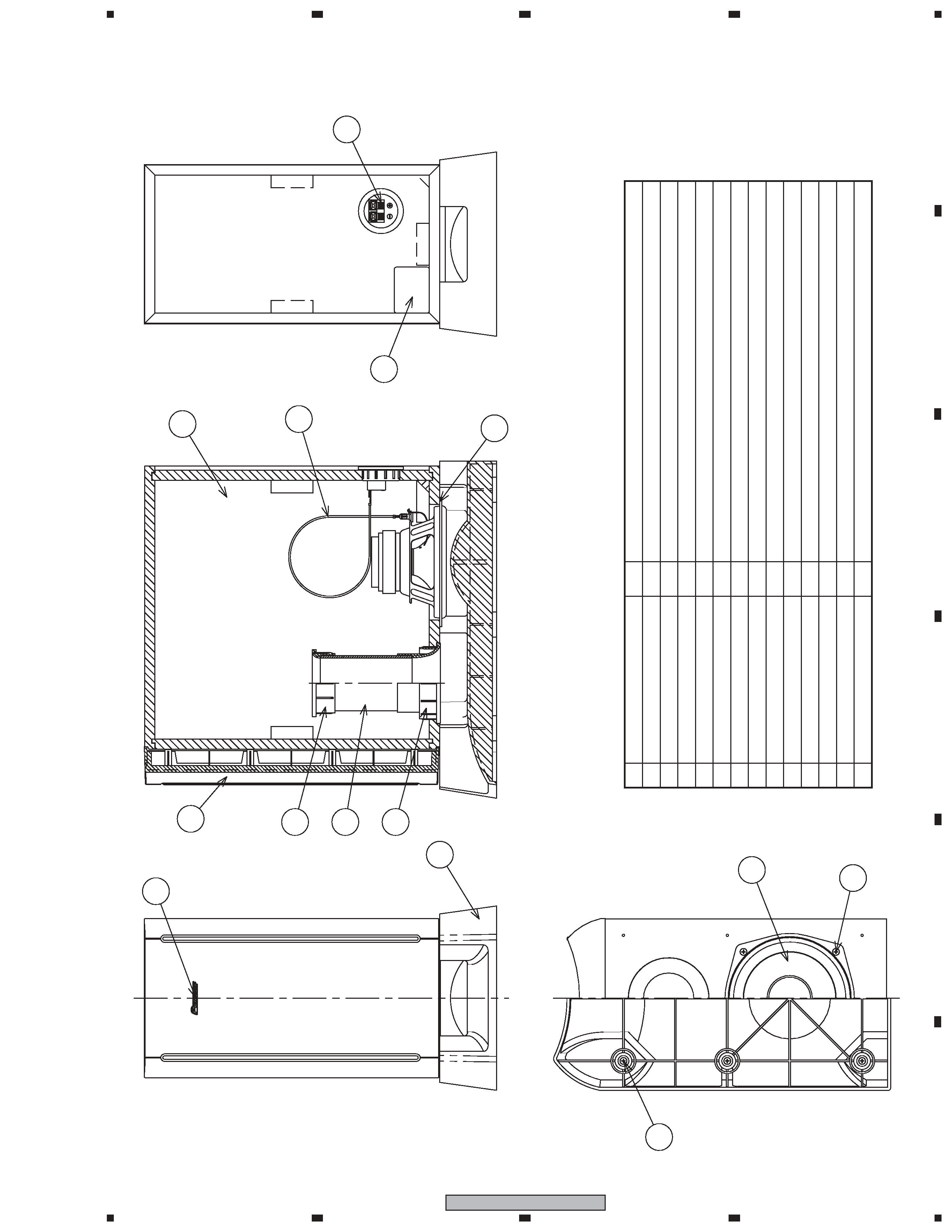
REASSEMBLY AND DISASSEMBLY
The cosmetic baffle assy is attached to the cabinet by its bosses.
To detach it, first remove the stand. Next pry it open by insert-
ing a flat blade screw driver into lower slot.
To attach it, press it to the cabinet.
The stand is attached to the cabinet by 6 external screws.
To detach it, unfasten those screws.
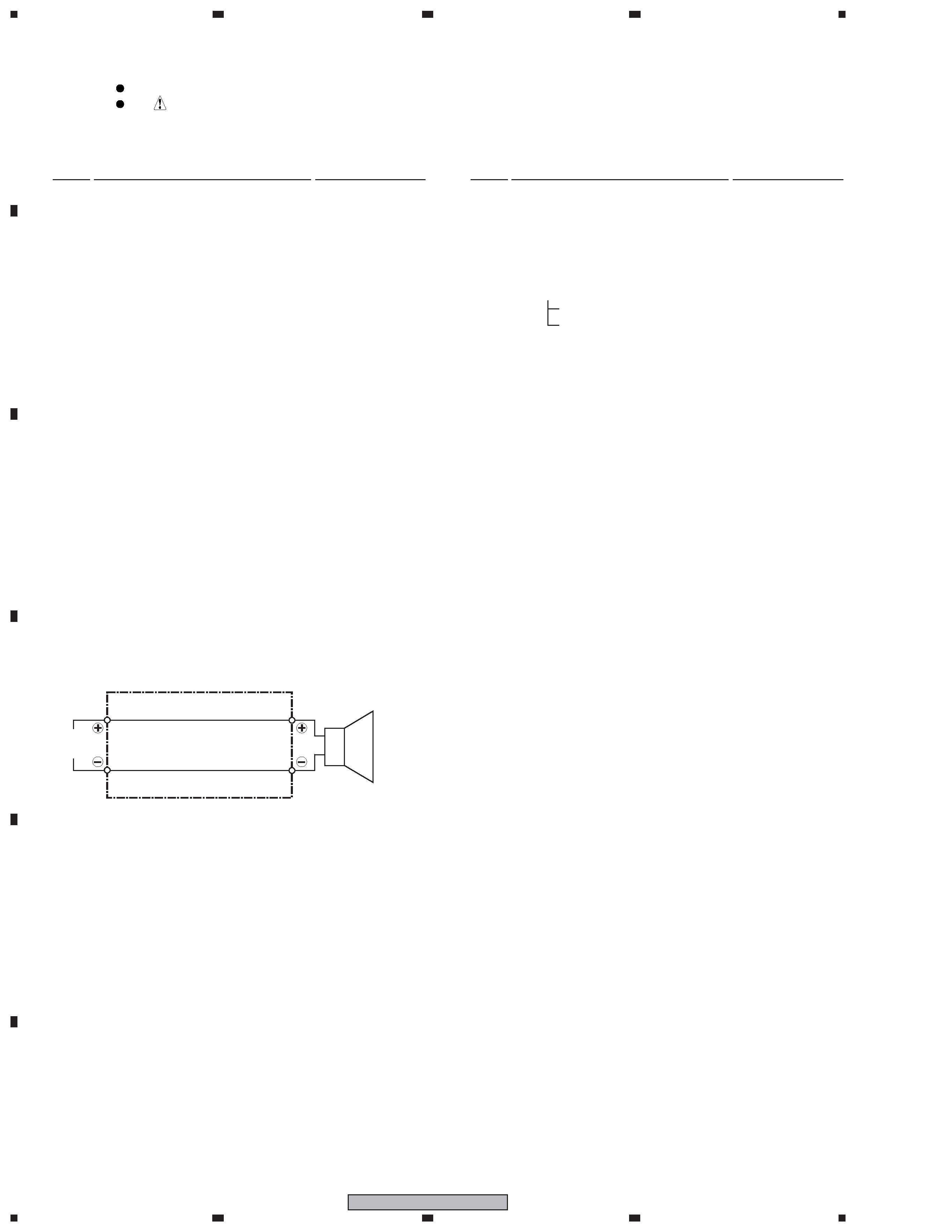
The speaker unit is attached to the cabinet by 4 external screws.
To detach it, first remove the stand. Then unfasten those
screws.
When attaching it, face its terminal toward the back board.
The input terminal is attached to the back board by press-fit-
ting.
To detach it, pry it open by inserting a flat blade screwdriver
into the lower side.
When attaching it, the red terminal is right-side.
SUBWOOFER SYSTEM
S-SW315
XCN