PDK-TS26
-- Checking materials included in package --
Please be sure to check that all of the following items are included in the package with your product. If for any reason there are
any items missing or items which fail to work properly, please contact PIONEER or the retailer at which you purchased the
product immediately for assistance.
PD
K-T
S26
Ch
eck
ing
ma
teri
als
inc
lud
ed
in
pac
kag
e
Ple
ase
be
sure
to
che
ck
tha
t all
of th
e fo
llow
ing
item
s a
re
inclu
ded
in
the
pac
kag
e w
ith
you
r pr
odu
ct. If
for
any
rea
son
the
re
are
any
item
s m
issin
g o
r ite
ms
wh
ich
fail
to
wor
k p
rop
erly
, ple
ase
con
tac
t P
IO
NE
ER
or th
e re
taile
r at
wh
ich
you
purc
has
ed
the
pro
duc
t im
me
dia
tely
for
ass
ista
nce
.
Op
era
ting
inst
ruc
tion
s (th
is
doc
um
ent)
Mo
nito
r a
ttac
hm
ent s
cre
ws
M6 ×
50 m
m (
4)
Sta
nd
ass
em
bly
scre
ws
M4 ×
10
mm
(8)
Sec
urin
g b
rac
kets
(2)
Fee
t (2
)
Bar
(1)
En
gli
sh
Op
era
tin
g In
stru
ctio
ns
Tab
le T
op
Sta
nd
......
......
......
......
......
......
......
......
......
......
......
......
.
Tha
nk
you
for
cho
osin
g to
pu
rch
ase
PIO
NE
ER
P
DK
-TS
26
tab
le t
op
sta
nd.
In
ord
er to
ens
ure
tha
t yo
u a
re
able
to
ma
ke
the
fulle
st p
oss
ible
use
of th
is p
rod
uct,
ple
ase
be
sure
to
rea
d th
is O
pera
ting
Inst
ruc
tion
s
befo
re
use
.
Afte
r re
adin
g, p
lace
this
ma
nua
l in
a e
asily
acc
ess
ed
loca
tion
for
futu
re
refer
enc
e.
This
pro
duc
t is
des
ign
ed
for
use
exc
lus
ive
ly
with
the
follo
win
g P
las
ma
Dis
play
s.
60-i
nch
Pla
sm
a D
isp
lay
s: P
DP
-60
7C
MX
/ P
DP
-60
MX
E20
No
tes
on
Ins
talla
tio
n Wo
rk:
This
pro
duc
t is
ma
rke
ted
ass
um
ing
tha
t it
is in
sta
lled
by
qua
lifie
d p
ers
onn
el w
ith
eno
ugh
skill
and
com
pete
nce
.
Alw
ays
hav
e a
n in
sta
llatio
n s
pec
ialis
t or
you
r de
ale
r in
sta
ll a
nd
set
up
the
pro
duc
t.
PIO
NE
ER
can
not
ass
um
e lia
biliti
es
for
dam
age
cau
sed
by
mis
take
in
inst
alla
tion
or m
oun
ting
, m
isu
se,
mo
dific
atio
n o
r a
natu
ral
disa
ste
r.
No
te
for
De
ale
rs:
Afte
r in
sta
llatio
n, b
e s
ure
to
deliv
er th
is m
anu
al to
the
cus
tom
er a
nd
exp
lain
to
the
cus
tom
er h
ow
to
han
dle
the
pro
duc
t.
Atte
ntio
n:
Sale
s A
gen
ts
and
Tec
hn
icia
ns
To
ens
ure
the
use
r s
safe
ty, b
e su
re
to
sele
ct a
pla
ce
suffi
cien
tly
stro
ng
to
bea
r th
e w
eig
ht o
f th
e P
lasm
a D
ispla
y a
nd
the
diffe
ren
t un
its.
Inst
alla
tion
sho
uld
be
perf
orm
ed
by
a m
inim
um
of th
ree
pers
ons
.
Be
care
ful
not
to
lose
rem
ove
d s
cre
ws,
etc
.
Do
not
inst
all o
r m
odif
y th
e p
rod
uct
oth
er t
han
spe
cifie
d. D
o
not
use
this
sta
nd
for
a P
lasm
a D
isp
lay
oth
er t
han
tho
se
des
ign
ate
d a
nd
do
not
mo
dify
it o
r us
e it
for
oth
er p
urp
ose
s.
Im
pro
per
inst
alla
tion
is e
xtre
me
ly d
ang
ero
us
bec
aus
e it
ma
y
res
ult
in
it fa
lling
ove
r or
oth
er a
ccid
ent.
Ins
talla
tion
Loc
atio
n
·S
ele
ct a
loca
tion
tha
t is
stro
ng
eno
ugh
to
sup
port
the
we
igh
t of
the
sta
nd
and
the
disp
lays
.
·
M
ake
sure
to
plac
e it
in
a le
vel
and
sta
ble
loca
tion
.
·
Do
not
inst
all it
outd
oors
, at
a h
ot s
prin
g, o
r ne
ar a
bea
ch.
·D
o n
ot in
sta
ll th
e s
tan
d w
here
it m
ay
be
sub
ject
ed
to
vib
ratio
n o
r sh
ock
.
Ass
em
blin
g a
nd
Ins
talla
tio
n
·
Ass
em
ble
the
sta
nd
in
acc
ord
anc
e w
ith
the
ass
em
bly
ins
tru
ctio
ns
and
sec
ure
ly
atta
ch
all
scre
ws
at
the
des
ign
ate
d lo
cat
ion
s.
Th
ere
hav
e b
een
cas
es
wh
ere
un
fore
see
n a
ccid
ent
s
suc
h a
s th
e e
qu
ipm
ent
bre
akin
g o
r fa
llin
g o
ver
occ
urre
d
afte
r th
e in
sta
llat
ion
of
the
dis
pla
y b
eca
use
the
sta
nd
wa
s n
ot
ins
talle
d a
s in
stru
cte
d.
·
Th
e d
isp
lay
m
ust
alw
ays
be
ins
talle
d b
y th
ree
or
m
ore
peo
ple
to
ass
ure
it is
ins
talle
d s
afe
ly.
·
Bef
ore
ins
talla
tio
n, t
urn
off
the
po
we
r fo
r th
e d
isp
lay
and
per
iph
era
l de
vic
es
the
n re
m
ove
the
po
we
r co
rd
plu
g fr
om
the
po
we
r o
utle
t.
Pre
ven
t ac
cide
nts
cau
sed
by
the
pro
duc
t fa
lling
ove
r by
takin
g
relia
ble
me
asu
res
to
pre
ven
t it
from
fallin
g o
ver.
Cau
tion
Sec
urin
g th
e P
las
ma
Dis
pla
y in
pla
ce
Atta
ch
the
sec
urin
g b
rac
kets
and
scre
ws
pro
vid
ed
with
the
sta
nd
to
the
Pla
sm
a
Dis
pla
y
in
the
loc
atio
ns
ind
ica
ted
in
the
acc
om
pan
yin
g d
iag
ram
, an
d th
en
use
sep
ara
te
com
me
rcia
lly
ava
ilab
le
scre
ws
(ey
e
scre
w)
and
wi
res
or
som
e
oth
er
sim
ilar
item
of
suff
icie
nt
stre
ngth
to
sec
ure
the
Pla
sm
a D
isp
lay
into
pla
ce
aga
inst
a w
all,
pilla
r, o
r so
me
oth
er s
urfa
ce
or o
the
rwis
e u
se
the
hole
s lo
cate
d a
t th
e re
ar o
f th
e st
and
to
fix
the
sta
nd
into
pla
ce.
(N
ote
tha
t th
ese
bra
cke
ts
and
scre
ws
are
not
use
d w
hen
usin
g a
sep
ara
tely
sold
ceili
ng
atta
chm
ent
unit
or w
all a
ttac
hm
ent
unit
.)
Be
sure
to
tak
e c
are
of th
e s
ecu
ring
wire
s w
hen
mo
vin
g
the
sta
nd
or P
lasm
a D
isp
lay.
No
te
tha
t th
e w
ires
and
scre
ws
nee
ded
to
sec
ure
the
Pla
sm
a D
isp
lay
aga
ins
t a
wa
ll o
r p
illa
r o
r a
gain
st th
e
sta
nd
are
not
pro
vid
ed
with
the
sta
nd,
and
tha
t th
e
pro
pe
r
ite
ms
mu
st
be
pu
rch
ase
d
se
pa
rate
ly
in
acc
ord
anc
e w
ith
the
typ
e o
f ob
jec
t or
surf
ace
aga
ins
t
wh
ich
the
mo
nito
r is
to
be
sec
ure
d.
Saf
ety
Pre
cau
tion
s
Sep
ara
tely
pu
rch
ase
d
scre
ws
Sec
urin
g b
rack
ets
Pub
lishe
d by
Pion
eer
Corp
orati
on.
Cop
yrigh
t ©
2006
Pion
eer
Corp
orati
on.
All rig
hts
rese
rved
.
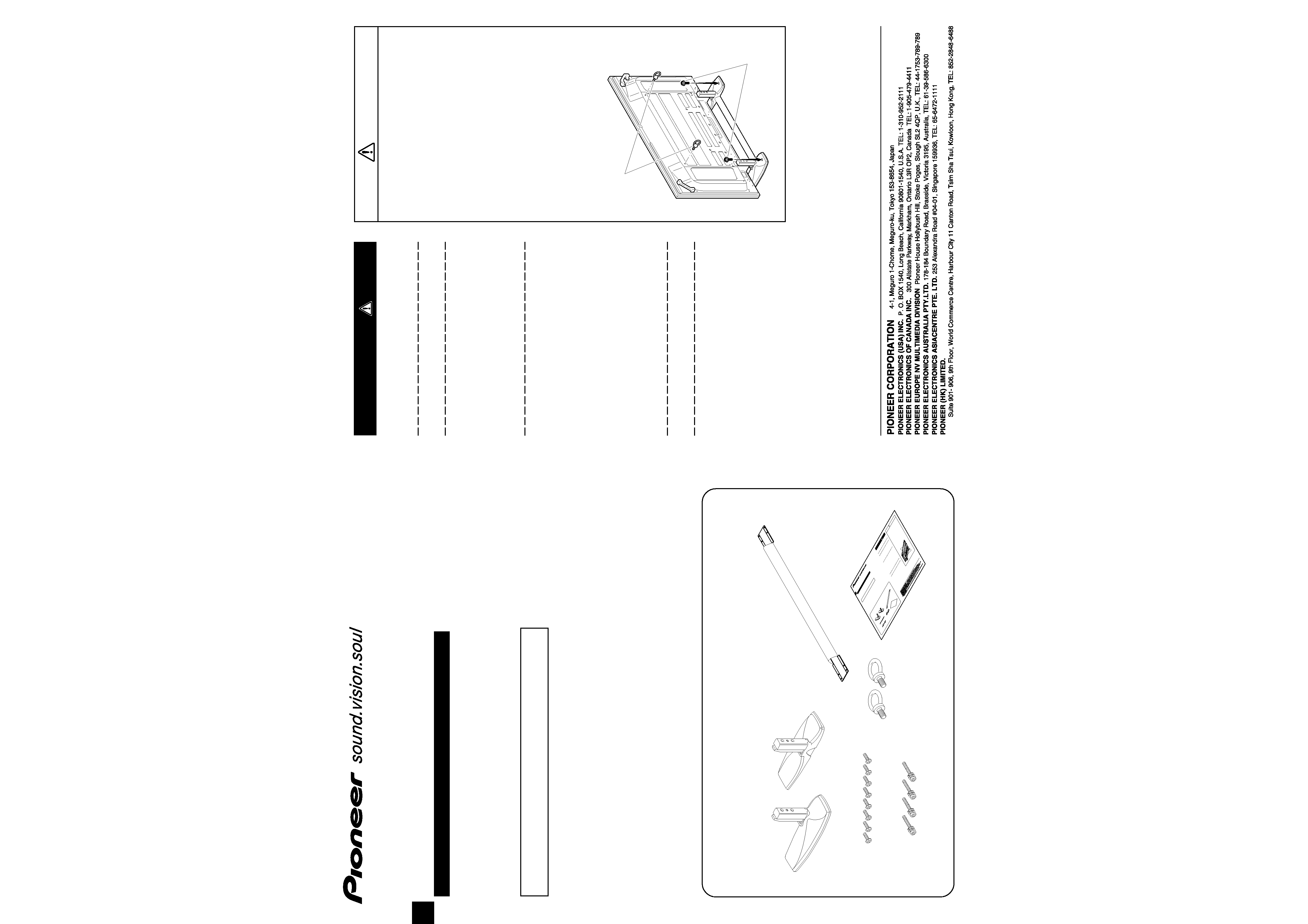
Operating instructions (this document)
Monitor attachment screws
M6
× 50 mm (4)
Stand assembly screws
M4
× 10 mm (8)
Securing brackets (2)
Feet (2)
Bar (1)
English
Operating Instructions
Table Top Stand .........................................................................
Thank you for choosing to purchase PIONEER PDK-TS26 table top stand.
In order to ensure that you are able to make the fullest possible use of this product, please be sure to read this Operating Instructions
before use.
After reading, place this manual in a easily accessed location for future reference.
This product is designed for use exclusively with the following Plasma Displays.
¶ 60-inch Plasma Displays: PDP-607CMX / PDP-60MXE20
Notes on Installation Work:
This product is marketed assuming that it is installed by qualified personnel with enough skill and competence.
Always have an installation specialist or your dealer install and set up the product.
PIONEER cannot assume liabilities for damage caused by mistake in installation or mounting, misuse, modification or a natural
disaster.
Note for Dealers:
After installation, be sure to deliver this manual to the customer and explain to the customer how to handle the product.
Attention: Sales Agents and Technicians
To ensure the user's safety, be sure to select a place sufficiently strong to bear the weight of the Plasma Display and the different units.
Installation should be performed by a minimum of three persons.
Be careful not to lose removed screws, etc.
Do not install or modify the product other than specified. Do
not use this stand for a Plasma Display other than those
designated and do not modify it or use it for other purposes.
Improper installation is extremely dangerous because it may
result in it falling over or other accident.
Installation Location
· Select a location that is strong enough to support the
weight of the stand and the displays.
· Make sure to place it in a level and stable location.
· Do not install it outdoors, at a hot spring, or near a beach.
· Do not install the stand where it may be subjected to
vibration or shock.
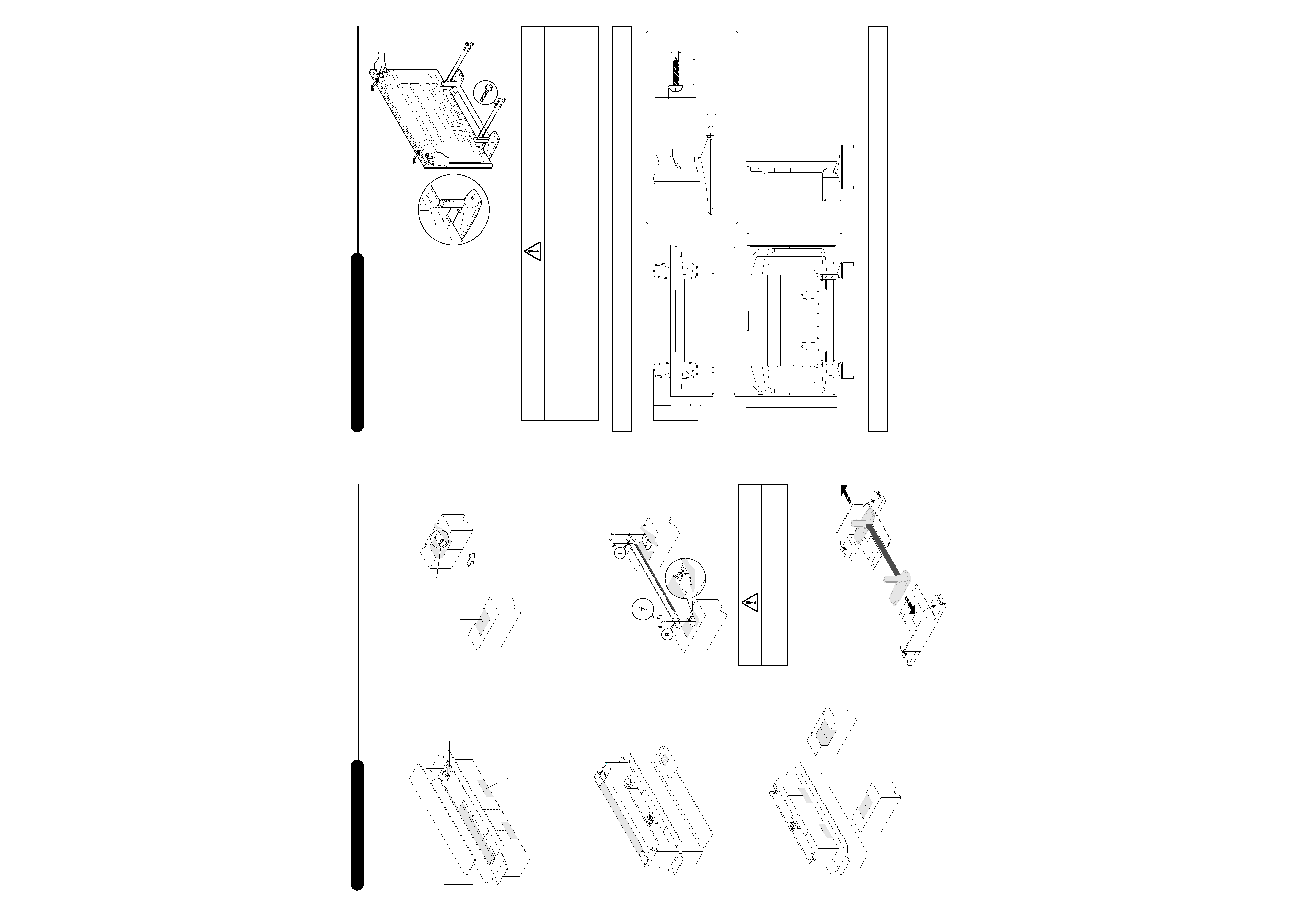
Assembling and Installation
· Assemble the stand in accordance with the assembly
instructions and securely attach all screws at the
designated locations.
There have been cases where unforeseen accidents
such as the equipment breaking or falling over occurred
after the installation of the display because the stand
was not installed as instructed.
· The display must always be installed by three or more
people to assure it is installed safely.
· Before installation, turn off the power for the display
and peripheral devices then remove the power cord
plug from the power outlet.
Prevent accidents caused by the product falling over by taking
reliable measures to prevent it from falling over.
Caution
Securing the Plasma Display in place
Attach the securing brackets and screws provided with
the stand to the Plasma Display in the locations
indicated in the accompanying diagram, and then use
separate commercially available screws (eye screw)
and wires or some other similar item of sufficient
strength to secure the Plasma Display into place against
a wall, pillar, or some other surface or otherwise use the
holes located at the rear of the stand to fix the stand into
place. (Note that these brackets and screws are not
used when using a separately sold ceiling attachment
unit or wall attachment unit.)
Be sure to take care of the securing wires when moving
the stand or Plasma Display.
Note that the wires and screws needed to secure the
Plasma Display against a wall or pillar or against the
stand are not provided with the stand, and that the
proper items must be purchased separately in
accordance with the type of object or surface against
which the monitor is to be secured.
Safety Precautions
Separately purchased
screws
Securing brackets
Published by Pioneer Corporation.
Copyright © 2006 Pioneer Corporation.
All rights reserved.