ORDER NO.
PIONEER CORPORATION 4-1, Meguro 1-chome, Meguro-ku, Tokyo 153-8654, Japan
PIONEER ELECTRONICS (USA) INC. P.O. Box 1760, Long Beach, CA 90801-1760, U.S.A.
PIONEER EUROPE NV Haven 1087, Keetberglaan 1, 9120 Melsele, Belgium
PIONEER ELECTRONICS ASIACENTRE PTE. LTD. 253 Alexandra Road, #04-01, Singapore 159936
PIONEER CORPORATION 2006
RRV3455
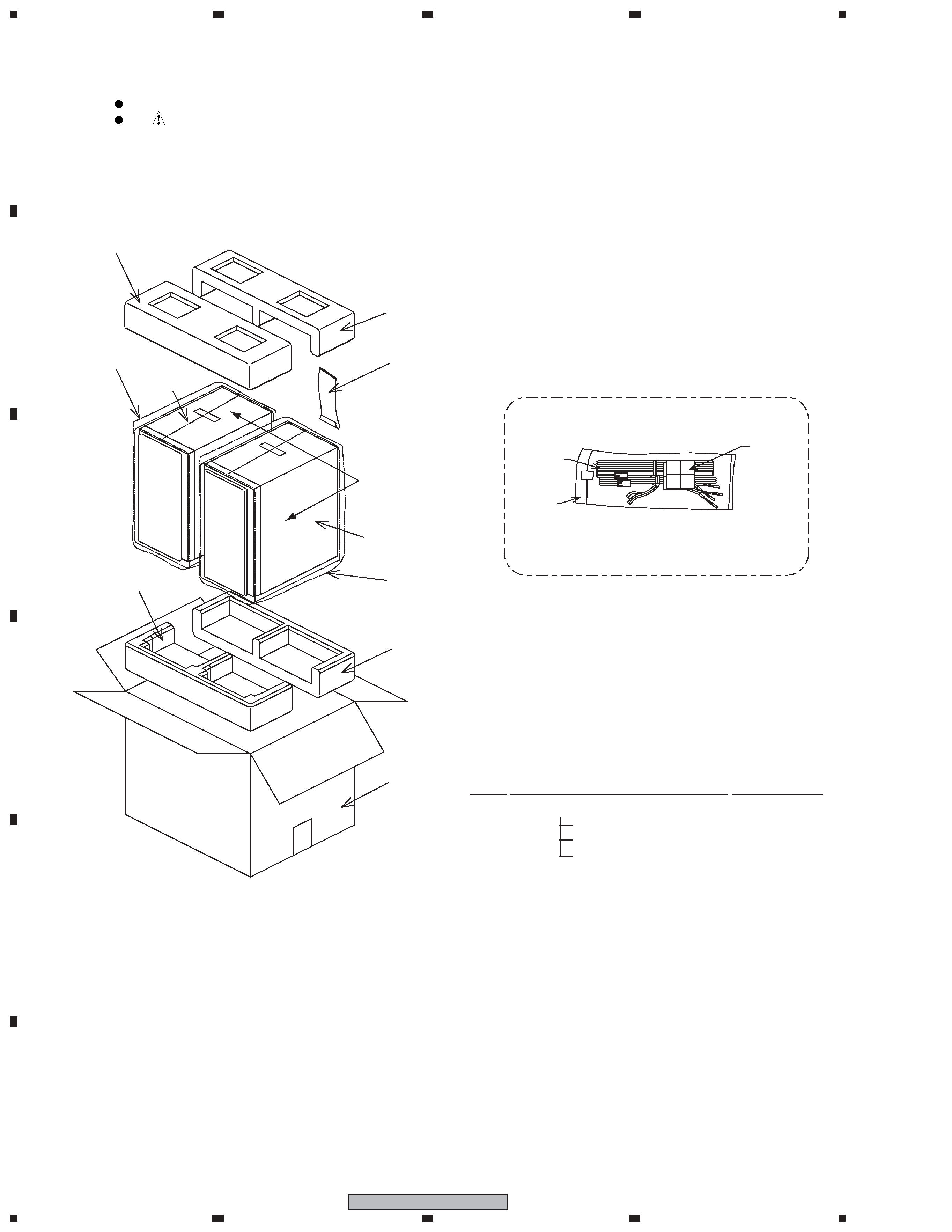
1. REASSEMBLY AND DISASSEMBLY PRECAUTIONS
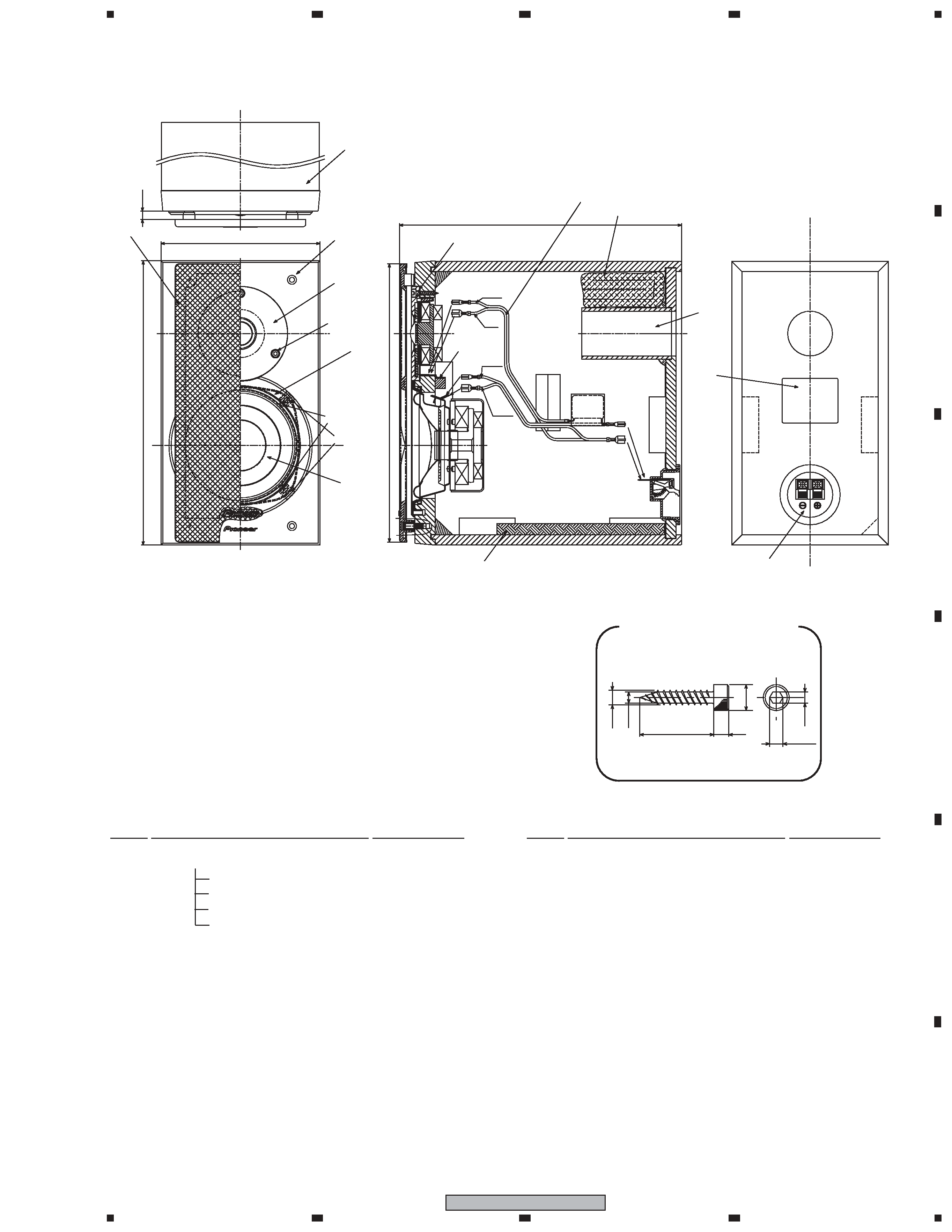
GRILLE
The grille is attached to the cabinet by catches. Detach by pull-
ing it toward you.
TWEETER
The woofer is attached to the baffle by 3 external screws.
To detach the tweeter, unfasten those screws by hexagonal
wrench.
When re-attaching it, face its terminal downward.
WOOFER
The woofer is attached to the baffle by 4 screws between the
cosmetic ring and baffle board.
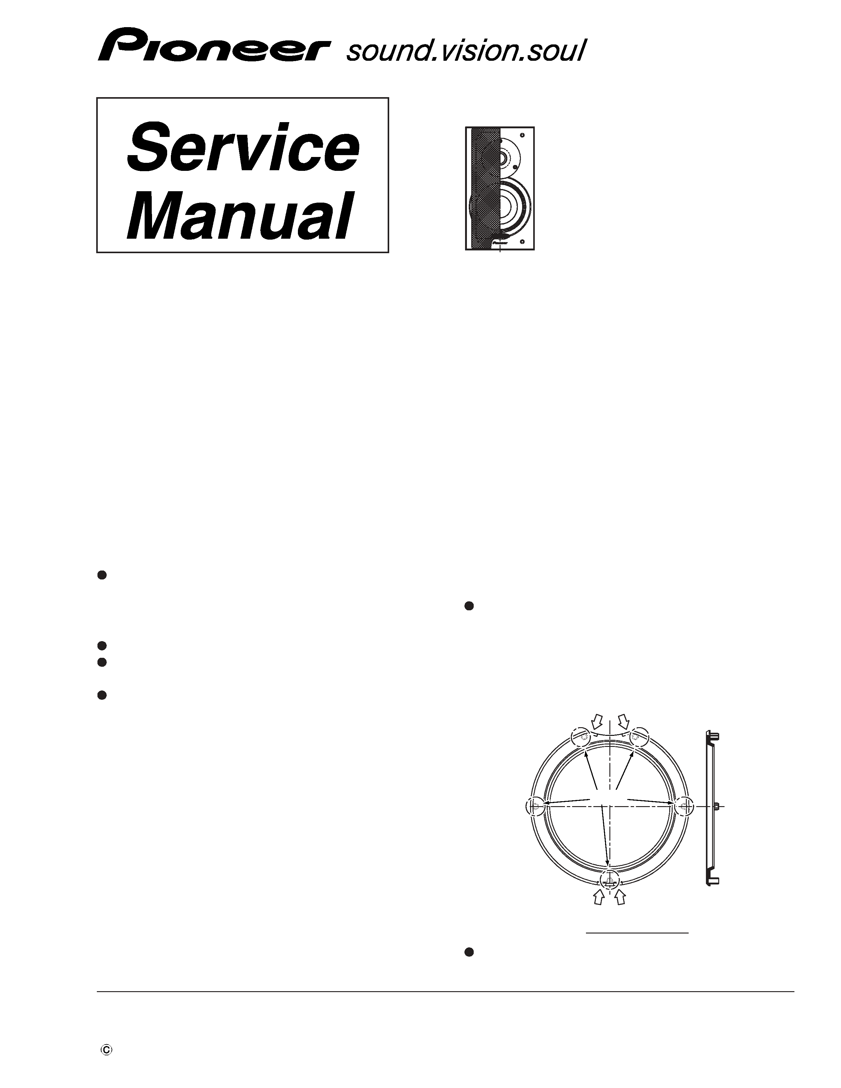
To detach it, first remove tweeter . Then remove cosmetic ring .
1.
The cosmetic ring is attached to the baffle by its bosses
(5pcs).
2.
Pry it open by inserting a flat blade screwdriver into upper
and lower slot.
3.
Unfasten those screws.
When re-attaching it, face its terminal upward.
Boss
Fig.1 cosmetic ring
Slot
Slot
S-MF5
XJC/E
SPEAKER SYSTEM
T ZZS JULY 2006 Printed in Japan