5
DV-410V-K
5
6
7
8
5
6
7
8
A
B
C
D
E
F
CONTENTS
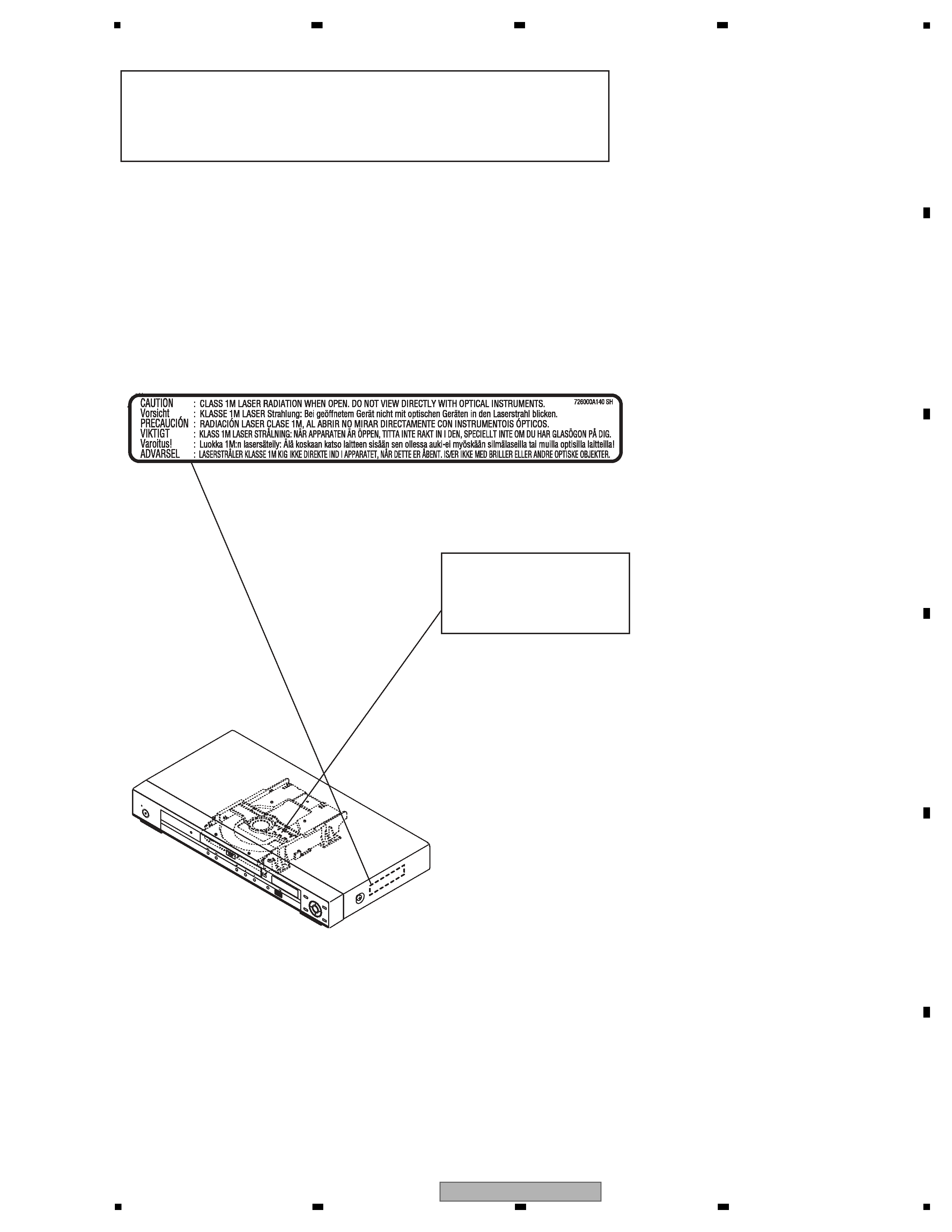
SAFETY INFORMATION.......................................................................................................................................................... 2
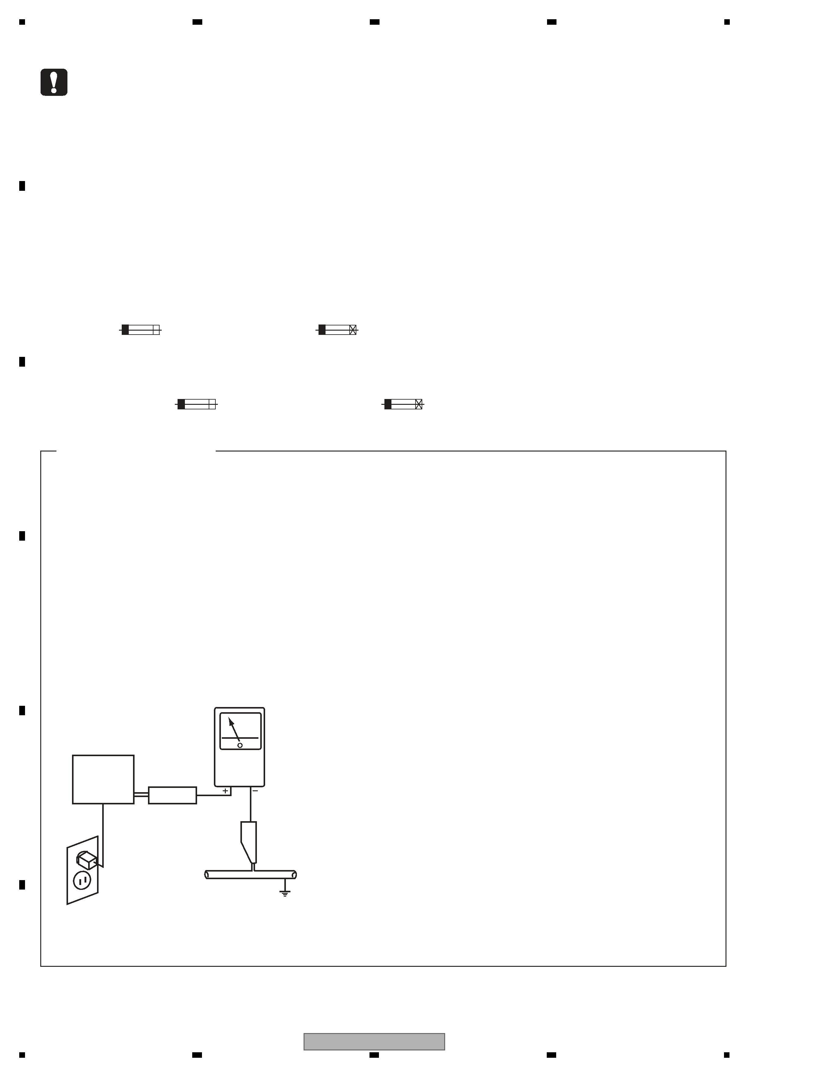
1. SERVICE PRECAUTIONS .................................................................................................................................................... 6
2. SPECIFICATIONS................................................................................................................................................................. 8
2.1 ACCESSORIES .............................................................................................................................................................. 8
2.2 SPECIFICATIONS .......................................................................................................................................................... 9
2.3 DISC/CONTENT FORMAT ........................................................................................................................................... 10
2.4 PANEL FACILITILES..................................................................................................................................................... 12
3. BASIC ITEMS FOR SERVICE ............................................................................................................................................ 14
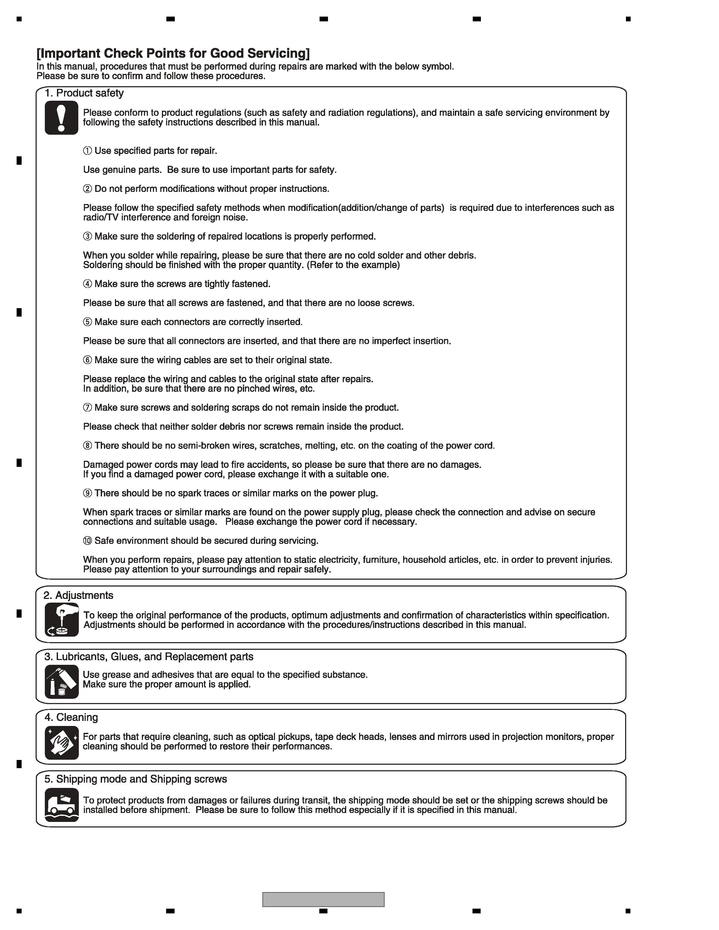
3.1 CHECK POINTS AFTER SERVICING ......................................................................................................................... 14
3.2 PCB LOCATIONS ......................................................................................................................................................... 15
3.3 JIGS LIST ..................................................................................................................................................................... 16
4. BLOCK DIAGRAM .............................................................................................................................................................. 18
4.1 OVERALL WIRING DIAGRAM ..................................................................................................................................... 18
4.2 OVERALL BLOCK DIAGRAM....................................................................................................................................... 20
4.3 DVD LOADER/MPEG BLOCK DIAGRAM .................................................................................................................... 21
4.4 POWER BLOCK DIAGRAM ......................................................................................................................................... 22
5. DIAGNOSIS ........................................................................................................................................................................ 23
5.1 TROUBLE SHOOTING................................................................................................................................................. 23
5.2 METHOD FOR DIAGNOSING DEGRADATION OF THE LDS ON THE PICKUP ASSY ............................................. 27
6. SERVICE MODE ................................................................................................................................................................. 28
6.1 SERVICE MODE PROCEDURE .................................................................................................................................. 28
6.2 SERVICE MODE IN...................................................................................................................................................... 29
6.3 DISPLAY SPECIFICATION OF THE SERVICE MODE ................................................................................................ 30
6.4 FUNCTIONAL SPECIFICATION OF THE SHORTCUT KEY ....................................................................................... 31
6.5 FUNCTIONAL SPECIFICATION OF THE SERVICE MODE ........................................................................................ 32
7. DISASSEMBLY ................................................................................................................................................................... 33
7.1 EXTERIOR SECTION .................................................................................................................................................. 33
7.2 DVD DECK SECTION .................................................................................................................................................. 34
8. EACH SETTING AND ADJUSTMENT ................................................................................................................................ 38
8.1 ADJUSTMENT.............................................................................................................................................................. 38
8.2 RE-WRITE FOR DVD FIRMWAVE ............................................................................................................................... 38
9. EXPLODED VIEWS AND PARTS LIST............................................................................................................................... 40
9.1 PACKING ...................................................................................................................................................................... 40
9.2 EXTERIOR SECTION .................................................................................................................................................. 42
9.3 06 DVD MECHA SECTION .......................................................................................................................................... 44
10. SCHEMATIC DIAGRAM .................................................................................................................................................... 46
10.1 DVD MT PCB ASSY(1/7) ............................................................................................................................................ 46
10.2 DVD MT PCB ASSY(2/7) ............................................................................................................................................ 48
10.3 DVD MT PCB ASSY(3/7) ............................................................................................................................................ 50
10.4 DVD MT PCB ASSY(4/7) ............................................................................................................................................ 52
10.5 DVD MT PCB ASSY(5/7) ............................................................................................................................................ 54
10.6 DVD MT PCB ASSY(6/7) ............................................................................................................................................ 56
10.7 DVD MT PCB ASSY(7/7) ............................................................................................................................................ 58
10.8 OPERATION PCB ASSY ............................................................................................................................................ 60
10.9 POWER PCB ASSY ................................................................................................................................................... 62
10.10 WAVEFORMS........................................................................................................................................................... 64
11. PCB CONNECTION DIAGRAM ........................................................................................................................................ 65
11.1 DVD MT PCB ASSY ................................................................................................................................................... 66
11.2 OPERATION PCB ASSY ............................................................................................................................................ 68
11.3 POWER PCB ASSY ................................................................................................................................................... 69
11.4 LOADING MOTOR and SW........................................................................................................................................ 71
12. PCB PARTS LIST .............................................................................................................................................................. 72