ORDER NO.
PIONEER CORPORATION 4-1, Meguro 1-chome, Meguro-ku, Tokyo 153-8654, Japan
PIONEER ELECTRONICS (USA) INC. P.O. Box 1760, Long Beach, CA 90801-1760, U.S.A.
PIONEER EUROPE NV Haven 1087, Keetberglaan 1, 9120 Melsele, Belgium
PIONEER ELECTRONICS ASIACENTRE PTE. LTD. 253 Alexandra Road, #04-01, Singapore 159936
PIONEER CORPORATION 2005
RRV3163
T ZZK JUNE 2005 Printed in Japan
SPEAKER SYSTEM
S-EV500V
XJM/E
S-EV500V XJM/NC
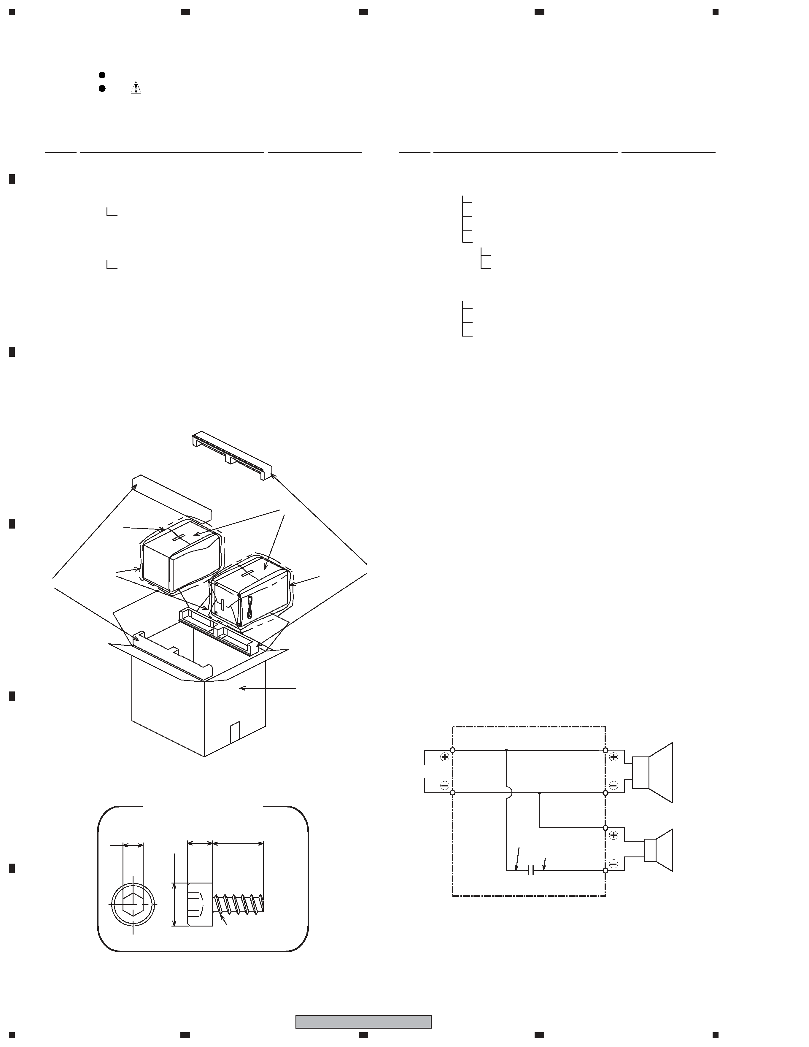
FOR PRECAUTION OF
REASSEMBLY AND DISASSEMBLY
CS Assy ( Front )
The grille assy is attached to the cabinet by catches. Detach by
pulling it toward you.
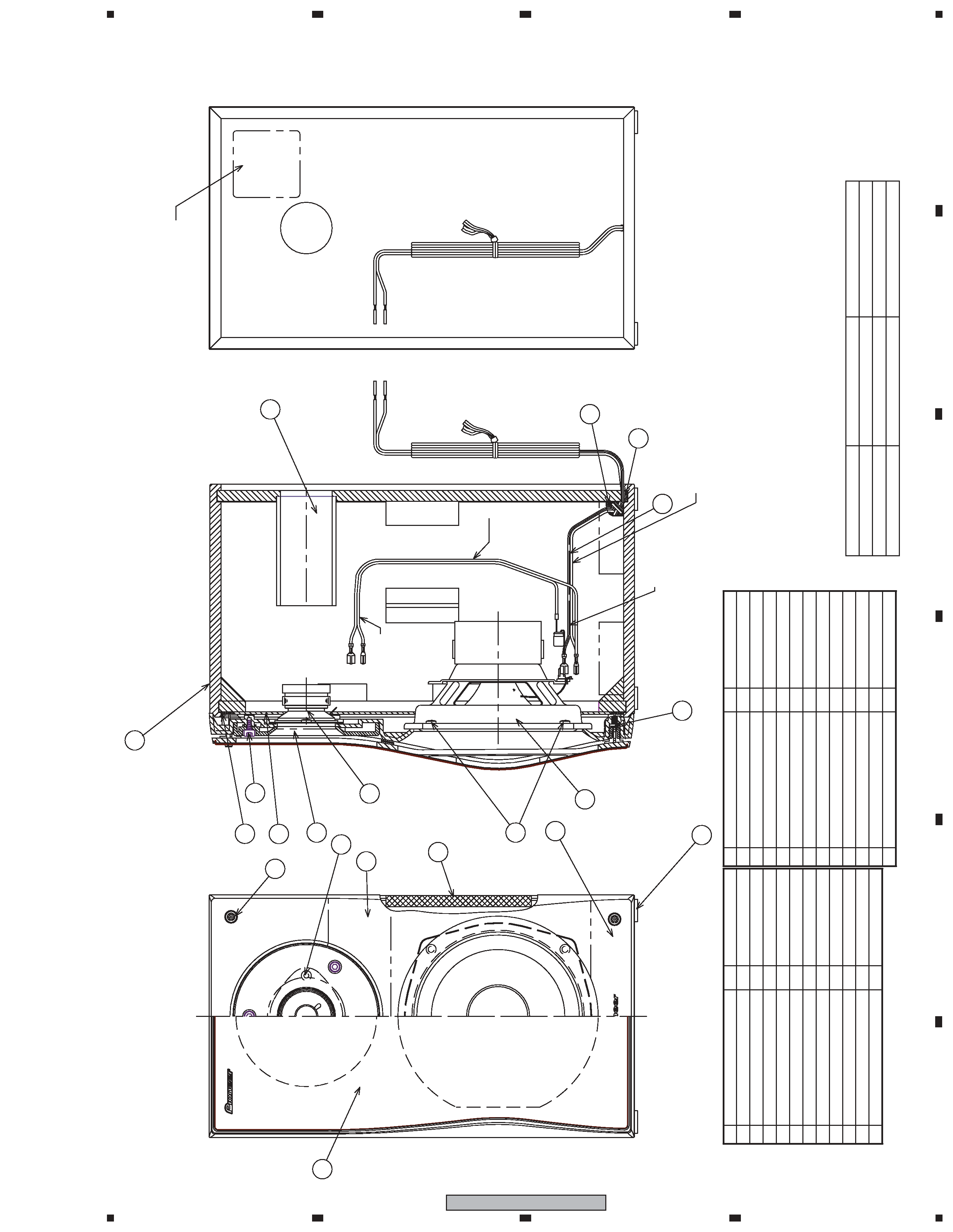
The catch is attached to the cosmetic baffle by press-fitting. To
detach it, insert a sharp-pointed tool like an eyeleteer into each
of side. To attach it, insert the holes of the cosmetic baffle assy
by press-fitting.
The cosmetic baffle is attached to the baffle by 4 external
screws. To detach it, first remove catches. Then unfasten those
screws.
The woofer is attached to the cosmetic baffle by 4 internal
screws. To detach it, first remove the cosmetic baffle. Then un-
fasten those screws. When attaching it, face its terminal down-
ward.
The tweeter is attached to the cosmetic baffle by 2 internal
screws. To detach it, first remove the cosmetic baffle. Then un-
fasten those screws. When attaching it, face its terminal down-
ward.