ORDER NO.
PIONEER CORPORATION 4-1, Meguro 1-chome, Meguro-ku, Tokyo 153-8654, Japan
PIONEER ELECTRONICS (USA) INC. P.O. Box 1760, Long Beach, CA 90801-1760, U.S.A.
PIONEER EUROPE NV Haven 1087, Keetberglaan 1, 9120 Melsele, Belgium
PIONEER ELECTRONICS ASIACENTRE PTE. LTD. 253 Alexandra Road, #04-01, Singapore 159936
PIONEER CORPORATION 2006
RRV3371
T ZZS AUG. 2006 Printed in Japan
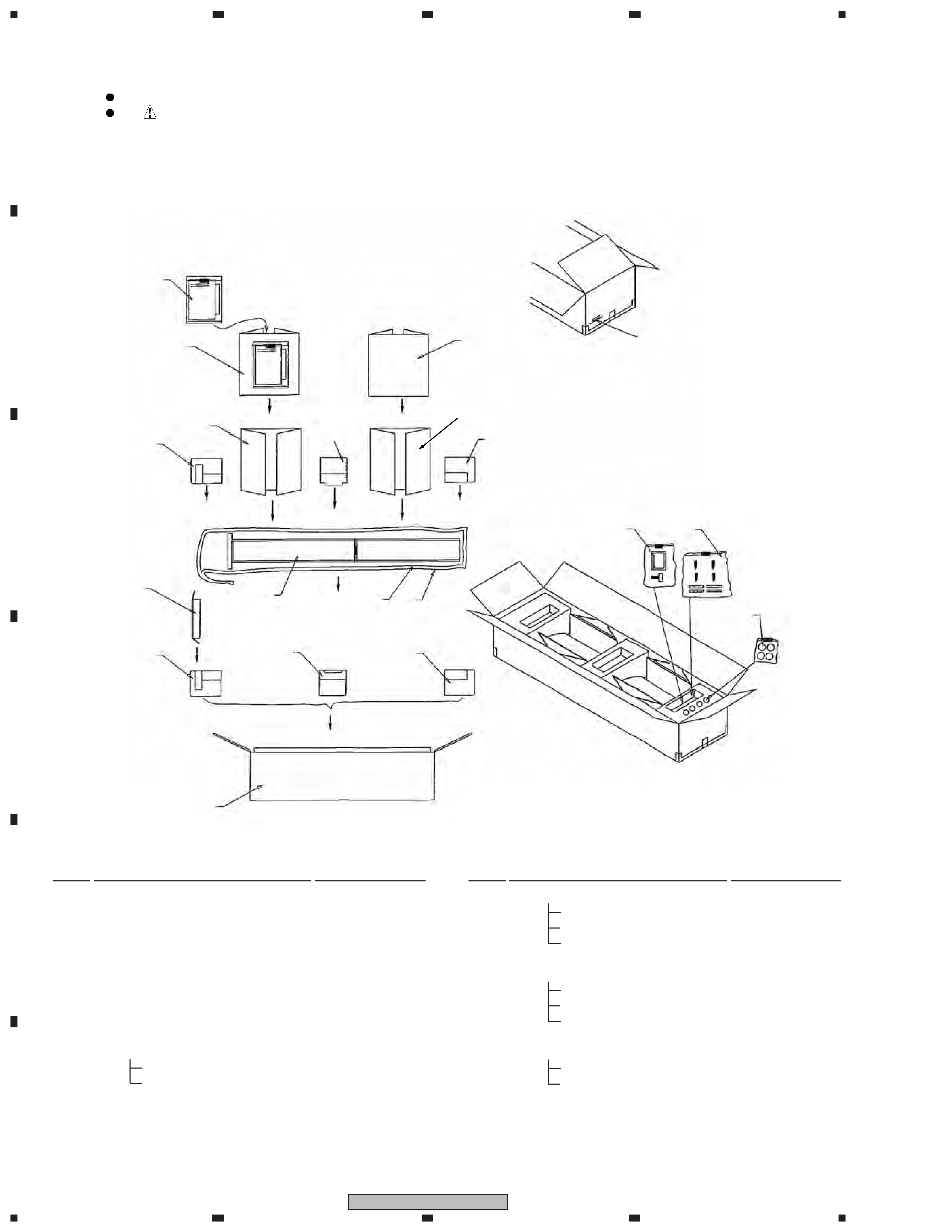
1. REASSEMBLY AND DISASSEMBLY PRECAUTIONS
The grilles are attached to the cabinet by catches. Detach by
pulling them toward you.
The base is attached to the cabinet by 7 external screws. To
detach it, unfasten those screws.
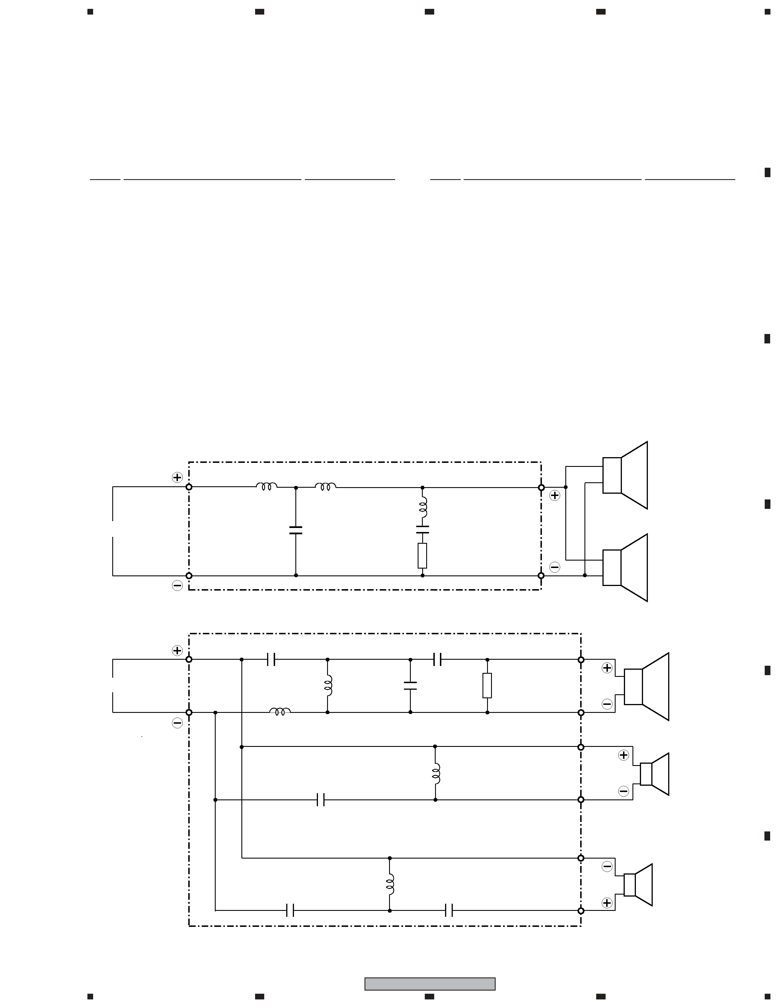
The networks are attached to the cabinet by 8 internal screws.
To detach them, first disconnect the cord to speakers. Next re-
move the base. Then unfasten those screws. When re-attaching
them, the network attached to the back side of the base is con-
nected to the terminal of High Pass Filter and the network at-
tached in the speaker system is connected to the terminal of
Low Pass Filter.
SPEAKER SYSTEM
S-EU8TB
XTW/E
The super-tweeter is attached to the baffle by 4 external screws.
To detach it, unfasten those screws. When re-attaching it, face
its terminal downward.
The mid-tweeter coaxial unit is attached to the baffle by 4 ex-
ternal screws. To detach it, unfasten those screws. When re-
attaching it, face its terminal leftward.
The woofers are attached to the baffle by 6 external screws. To
detach them, unfasten those screws. When re-attaching them,
face its terminal lower right.