ORDER NO.
PIONEER CORPORATION 4-1, Meguro 1-chome, Meguro-ku, Tokyo 153-8654, Japan
PIONEER ELECTRONICS (USA) INC. P.O. Box 1760, Long Beach, CA 90801-1760, U.S.A.
PIONEER EUROPE NV Haven 1087, Keetberglaan 1, 9120 Melsele, Belgium
PIONEER ELECTRONICS ASIACENTRE PTE. LTD. 253 Alexandra Road, #04-01, Singapore 159936
PIONEER CORPORATION 2006
RRV3436
T ZZM JUNE 2006 Printed in Japan
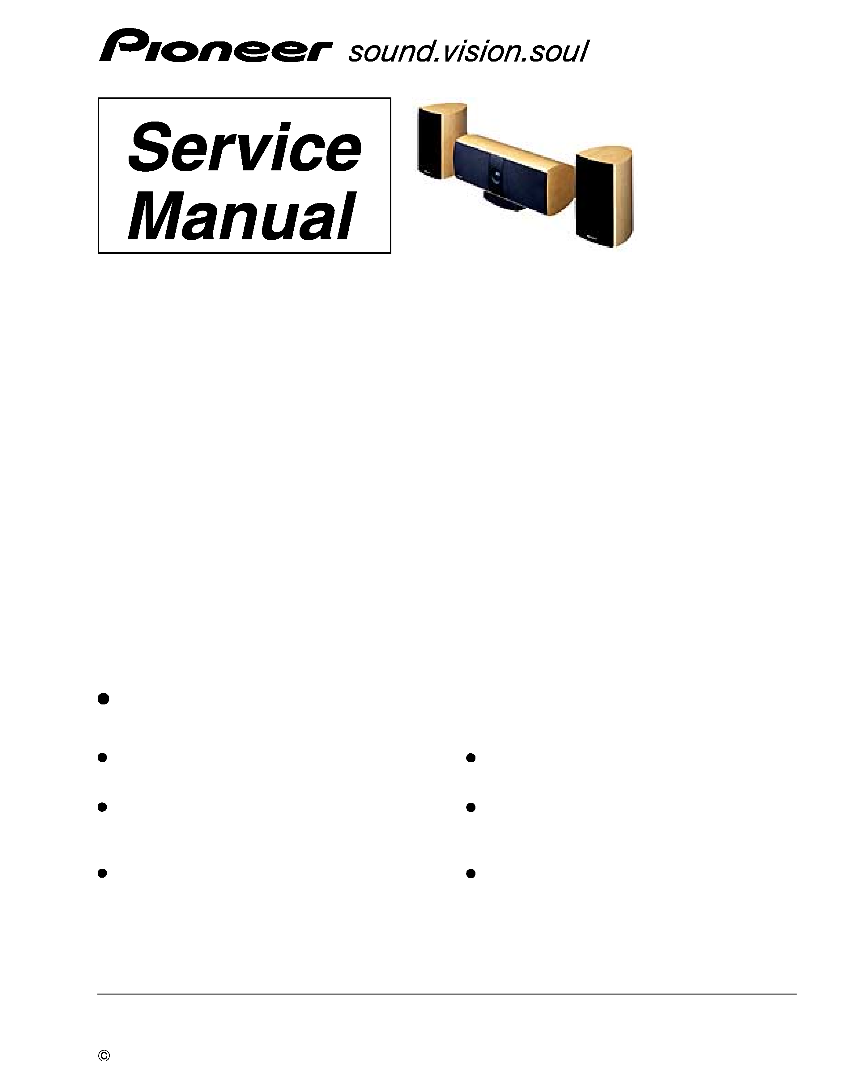
S-EU5CR
S-EU5CR
XTW/JP
SPEAKER SYSTEM
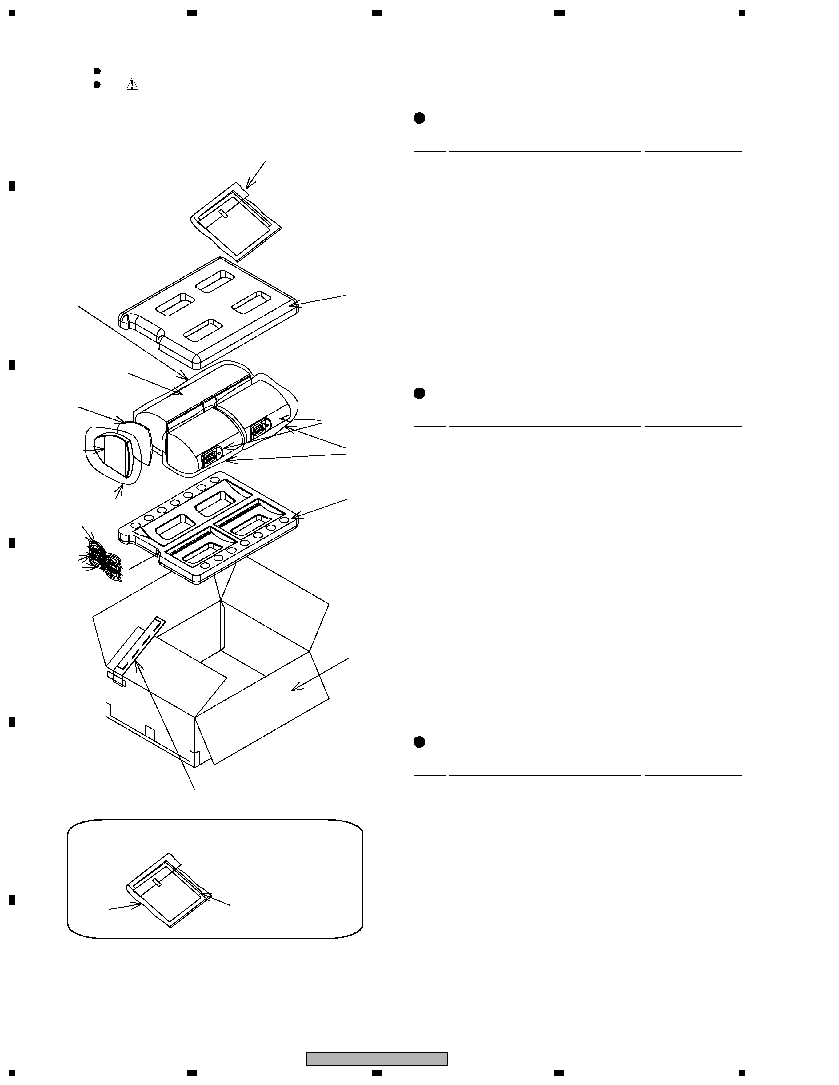
REASSEMBLY AND DISASSEMBLY PRECAUTIONS
The grille is attached to the cabinet by catches. Detach by pull-
ing it toward you.
The woofer is attached to the baffle by 4 external screws.
To detach it, unfasten those screws.
When attaching it, face its terminal toward the tweeter.
The tweeter is attached to the baffle by 2 internal screws.
To detach it, first remove the input terminal attached to the
cabinet by 2 screws. Then unfasten those screws.
When attaching it, face its terminal with marking upward.
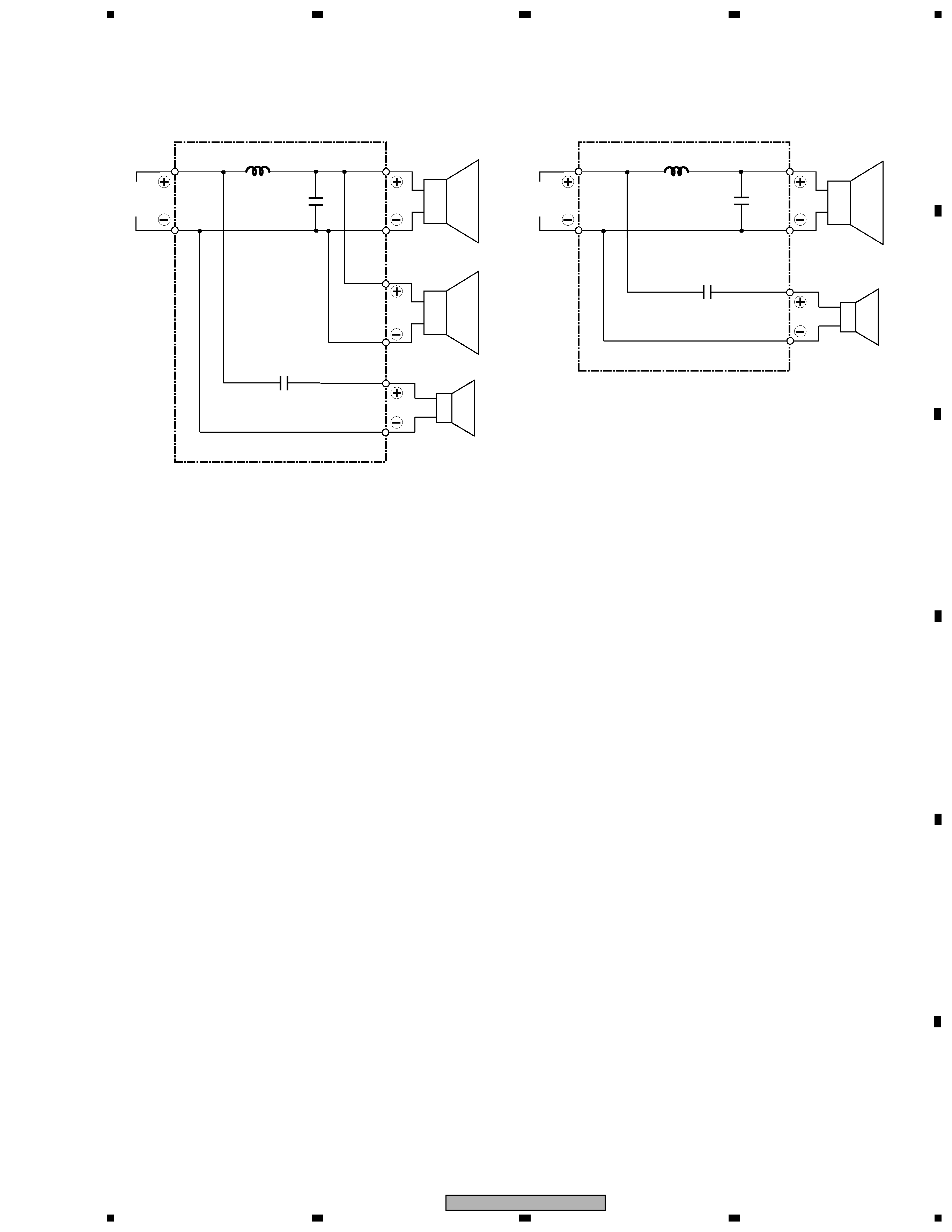
CENTER SPEAKER
REAR SPEAKER
The grille is attached to the cabinet by catches. Detach by pull-
ing it toward you.
The woofer is attached to the baffle by 4 external screws.
To detach it, unfasten those screws.
When attaching it, face its terminal downward.
The tweeter is attached to the baffle by 4 external screws.
To detach it, unfasten those screws.
When attaching it, face its terminal with marking rightward.