ORDER NO.
PIONEER CORPORATION 4-1, Meguro 1-chome, Meguro-ku, Tokyo 153-8654, Japan
PIONEER ELECTRONICS (USA) INC. P.O. Box 1760, Long Beach, CA 90801-1760, U.S.A.
PIONEER EUROPE NV Haven 1087, Keetberglaan 1, 9120 Melsele, Belgium
PIONEER ELECTRONICS ASIACENTRE PTE. LTD. 253 Alexandra Road, #04-01, Singapore 159936
PIONEER CORPORATION 2007
RRV3540
T ZZK JAN. 2007 Printed in Japan
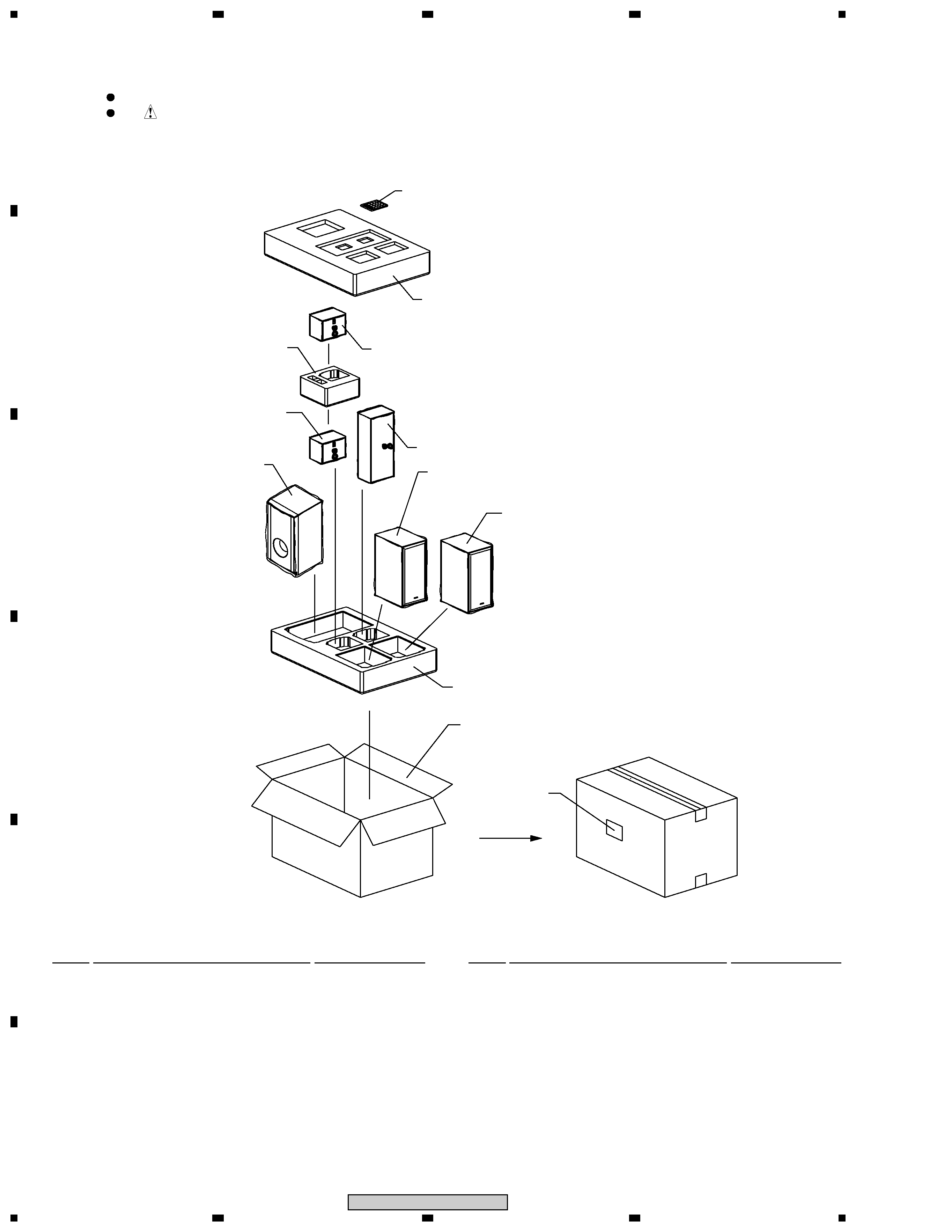
SPEAKER SYSTEM
1. REASSEMBLY AND DISASSEMBLY PRECAUTIONS
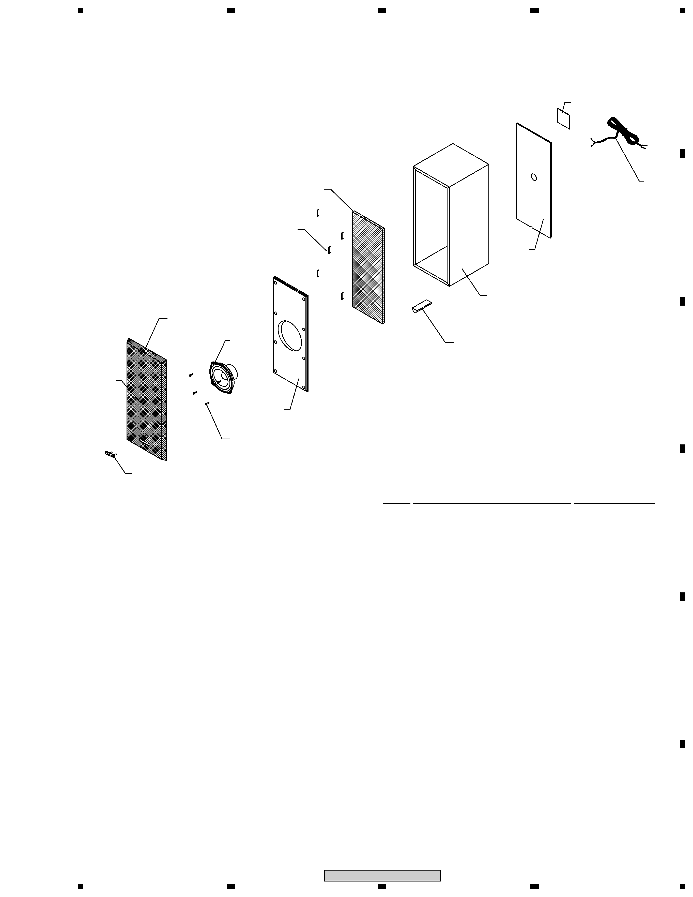
1.1 FRONT SPEAKER
The grille assy is attached to the cabinet by its bosses applied
with adhesive. To detach it, pry it open by inserting a flat blade
screwdriver into lower slot. To attach it, apply adhesive to the
holes on the baffle. Then press it to the baffle.
The speaker is attatched to the baffle by 4 external screws. To
detach it ,unfasten those screws. When attaching it, face its ter-
minal upward.
S-DV88
XJM/E
S-DV88 XMC
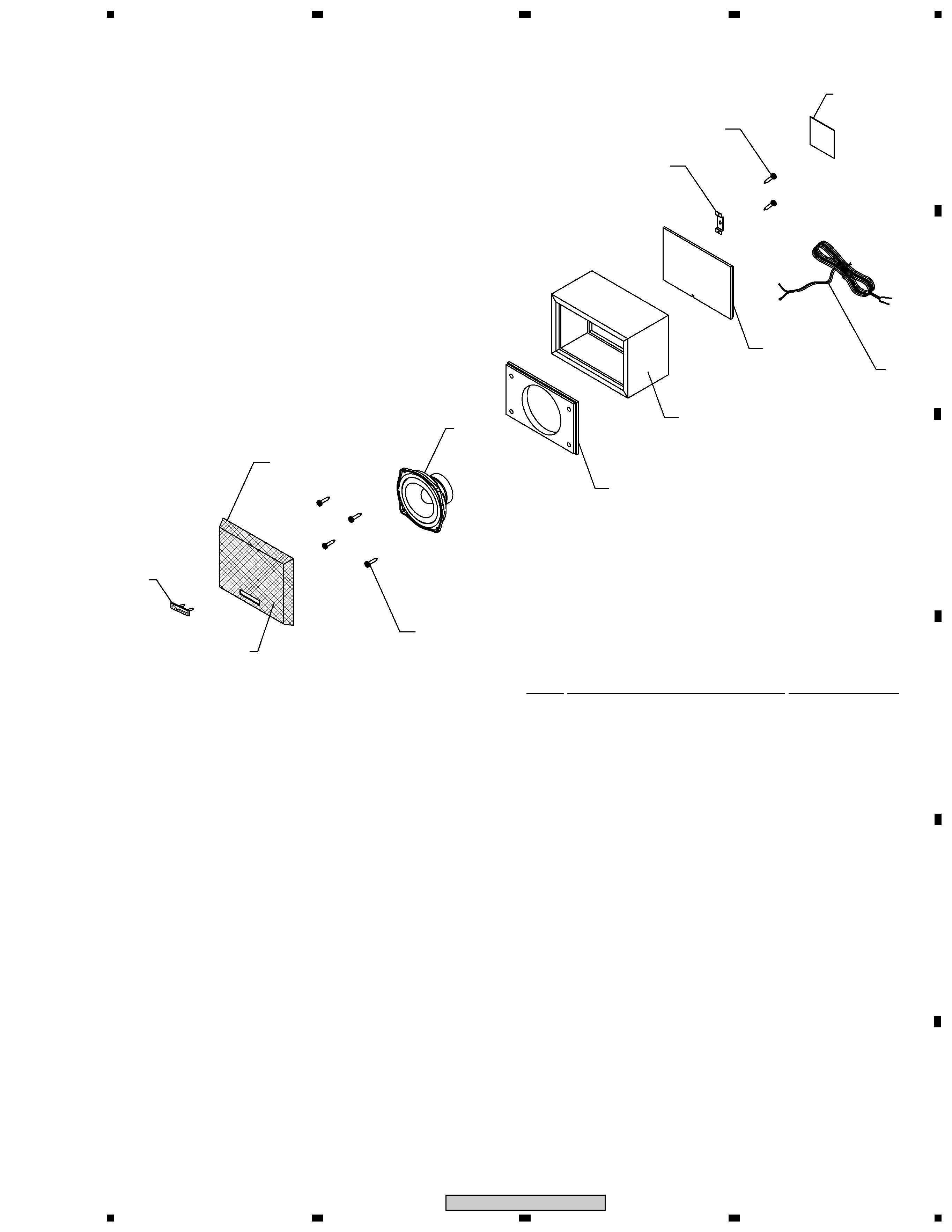
1.3 CENTER SPEAKER
The grille assy is attached to the cabinet by its bosses applied
with adhesive. To detach it, pry it open by inserting a flat blade
screwdriver into lower slot. To attach it, apply adhesive to the
holes on the baffle. Then press it to the bafle.
The speaker is attached to the baffle by 4 external screws. To
detach it ,unfasten those screws. When attaching it, face its ter-
minal leftward.
1.4 REAR SPEAKER
The grille assy is attached to the cabinet by its bosses applied
with adhesive. To detach it, pry it open by inserting a flat blade
screwdriver into lower slot. To attach it, apply adhesive to the
holes on the baffle. Then press it to the bafle.
The speaker is attached to the baffle by 4 external screws. To
detach it ,unfasten those screws. When attaching it, face its ter-
minal leftward.
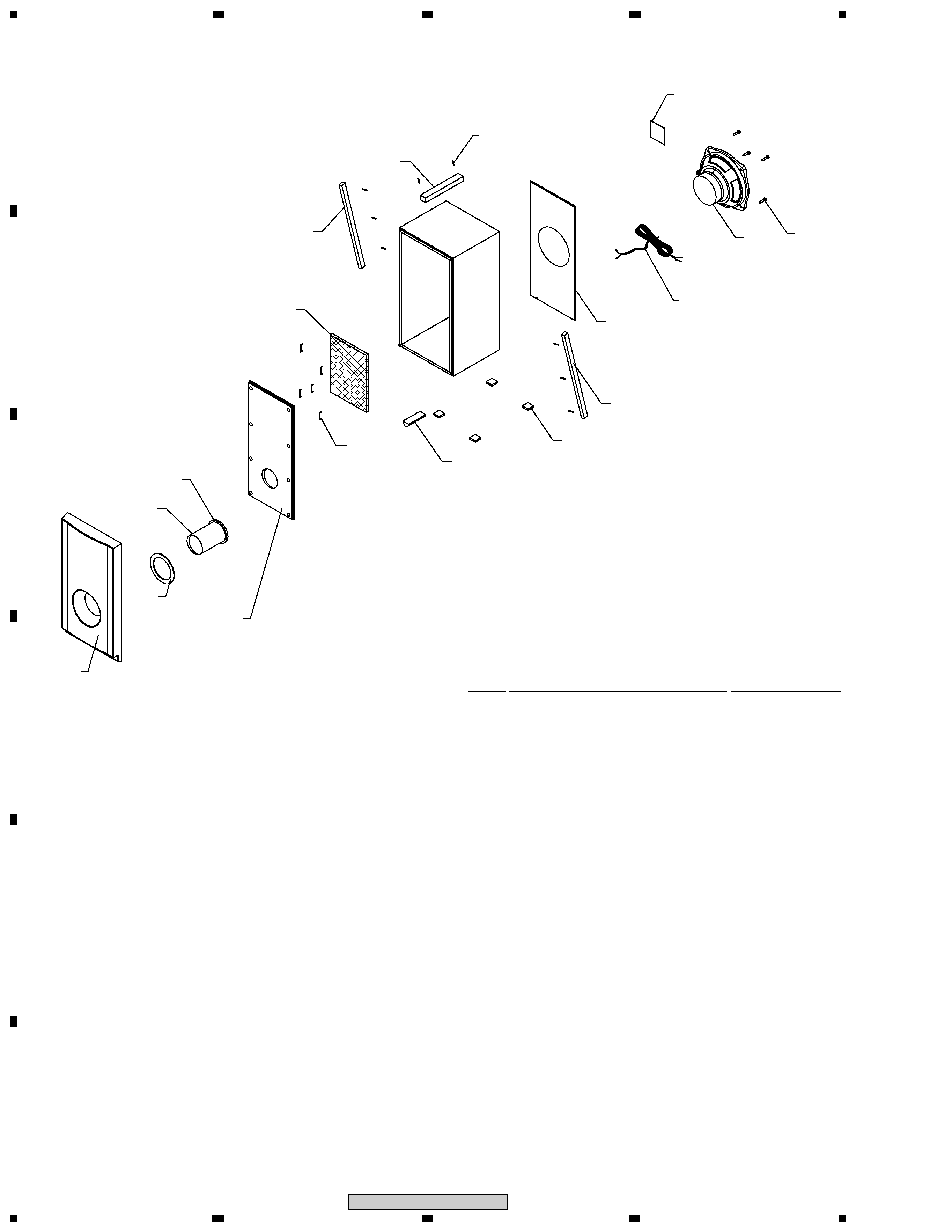
1.2 SUBWOOFER
The woofer is attached to the rear baffle by 4 external screws.
To detach it ,unfasten those screws. When attaching it, face its
terminal downward.
FRONT
SUBWOOFER
CENTER
REAR