PIONEER S-DV232T/XJC/E Service Manual

Cover page of PIONEER S-DV232T/XJC/E Service Manual

Service Manual for PIONEER S-DV232T/XJC/E, downloadable as a PDF file.

Manual details

  • Immediate download after payment.
  • Delivered as a PDF file.
  • The manual has 8 pages
  • File size: 0.46 MB
  • Available language versions: English
  • Different language versions may vary sligthly in file size and page count.

We guarantee that...

  • our manuals are complete,
  • the manual includes circuit diagrams,
  • our manuals are checked with antivirus,
  • We'll issue refund if the manual is damaged, incomplete or unreadable (our refund policy)

Sample pages

Thumbnail of page 1Thumbnail of page 2Thumbnail of page 3Thumbnail of page 4
Thumbnail of page 5Thumbnail of page 6Thumbnail of page 7Thumbnail of page 8
Thumbnail of page 9
background image
ORDER NO.
PIONEER CORPORATION 4-1, Meguro 1-chome, Meguro-ku, Tokyo 153-8654, Japan
PIONEER ELECTRONICS (USA) INC. P.O. Box 1760, Long Beach, CA 90801-1760, U.S.A.
PIONEER EUROPE NV Haven 1087, Keetberglaan 1, 9120 Melsele, Belgium
PIONEER ELECTRONICS ASIACENTRE PTE. LTD. 253 Alexandra Road, #04-01, Singapore 159936
PIONEER CORPORATION 2005
RRV3175
T ­ ZZK JUNE 2005 Printed in Japan
SPEAKER SYSTEM
S-DV232T
XJC/E
S-DV232T XJC/NC
Front
Sub Woofer
Center
Surround
Component
System
Service Manual
Remarks
5.1CH SURROUND SYSTEM
HTZ-232DV/LFXJ, /NTXJ
RRV3214
DVD/CD RECEIVER
XV-DV232T/LFXJ, /NTXJ
RRV3211
SPEAKER SYSTEM
S-DV232T/XJC/E, /XJC/NC
RRV3175
This service manual
This product is component of system.
Component
System
Service Manual
Remarks
5.1CH SURROUND SYSTEM
HTZ-232DV/TDXJ/RB
RRV3213
DVD/CD RECEIVER
XV-DV232T/TDXJ/RB
RRV3210
SPEAKER SYSTEM
S-DV232T/XJC/E
RRV3175
This service manual
Component
System
Service Manual
Remarks
5.1CH SURROUND SYSTEM
HTZ-232DV/WLXJ
RRV3212
DVD/CD RECEIVER
XV-DV232T/WLXJ
RRV3202
SPEAKER SYSTEM
S-DV232T/XJC/NC
RRV3175
This service manual
background image
2
1
23
4
12
3
4
C
D
F
A
B
E
S-DV232T
FOR PRECAUTION OF
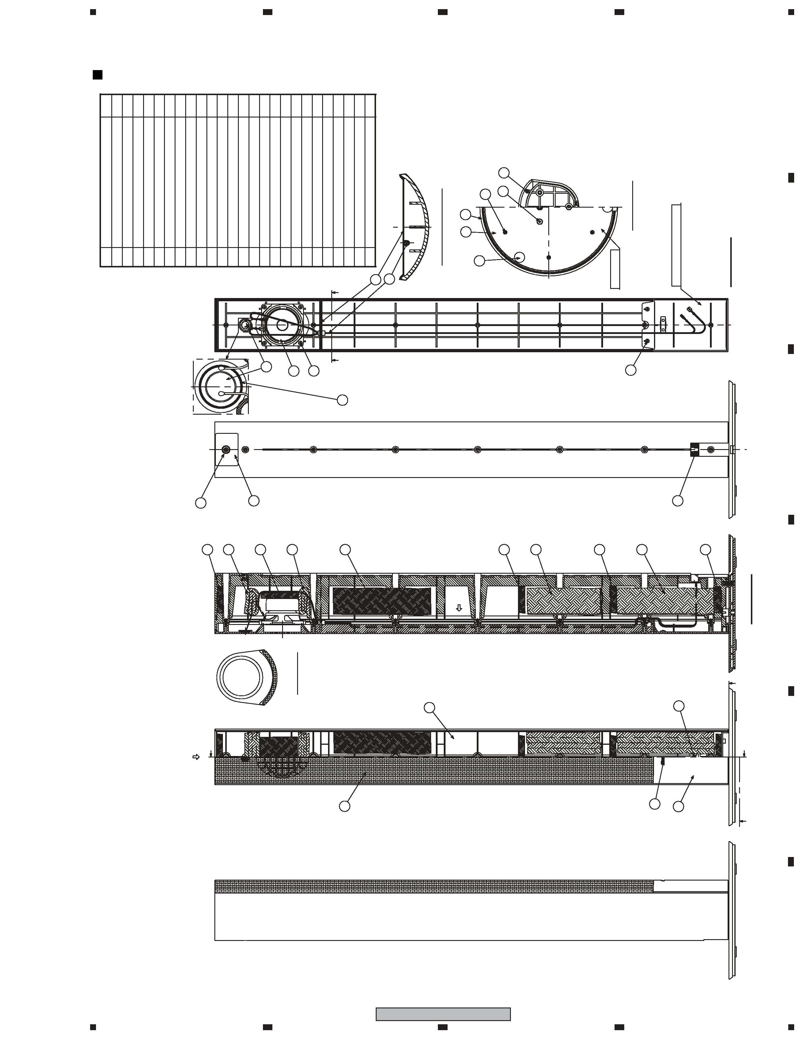
REASSEMBLY AND DISASSEMBLY
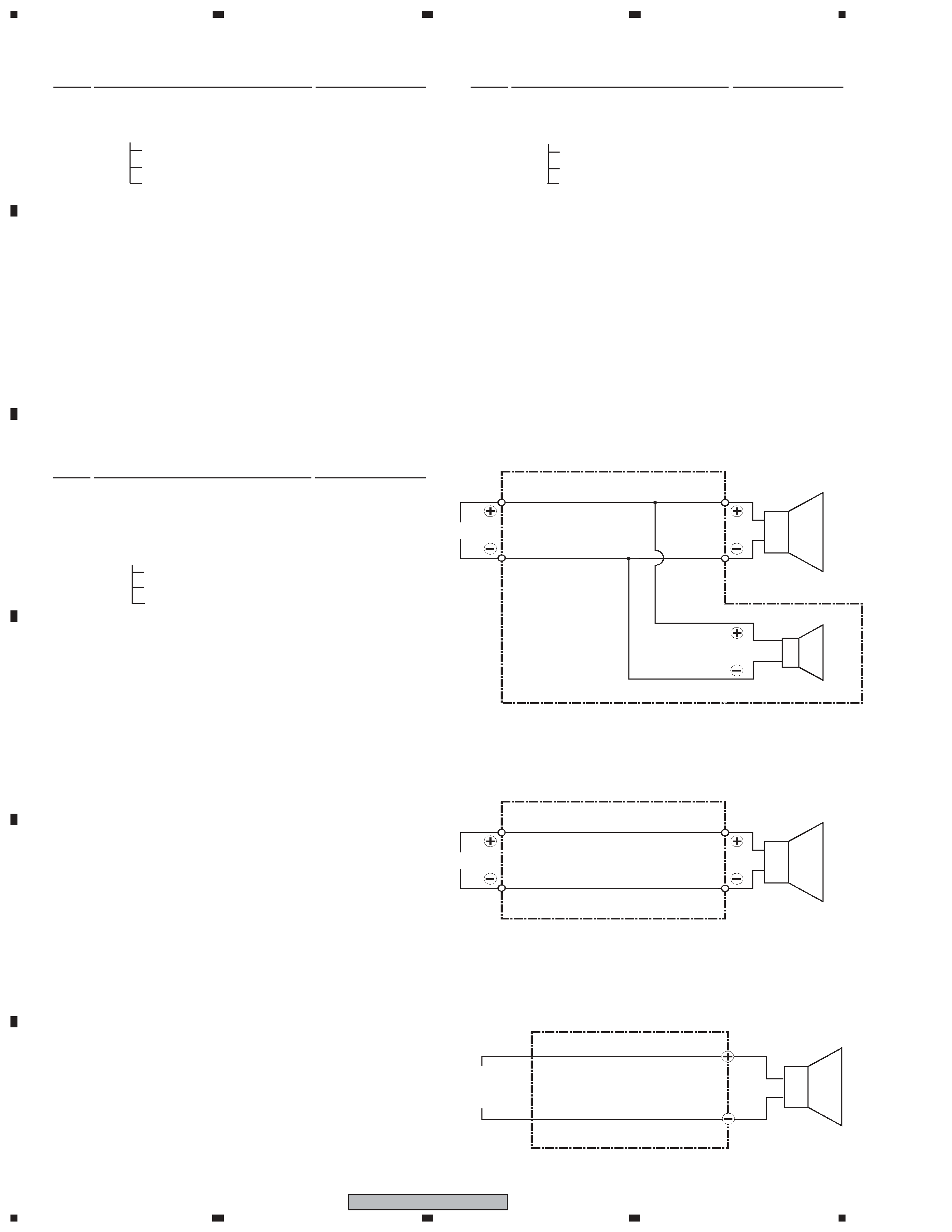
CS Assy ( Subwoofer )
The speaker unit is attached to the rear baffle by 4 external
screws. To detach it, unfasten those screws.
When attaching it, face its terminal rightward.
CS Assy ( Front )
The grille assy is attached to the cabinet by 9 external screws.
To detach it, first remove 3 screws of connection part with the
base assy. Next remove 2 screws of the cosmetic plate assy
lower side. Next remove 7 screws of the cabinet. Then carefully
disconnect the wires of the woofer mounted on the grille assy
and input terminal. To detach the cosmetic plate assy, remove 2
screws of connection part with the grille assy.
The woofer is attached to the grille by 4 internal screws. To
detach it, first unfasten those screws. Next remove the cable.
When attaching it, face its terminal upward.
The tweeter is attached to the baffle by adhesives. To exchange
the tweeter, do it with the grille assy.
The cosmetic plate assy is attached to the grille assy by 2 inter-
nal screws. To detach it, first remove the grille assy. Next un-
fasten those screws.
CS Assy ( Surround )
The grille assy is attached to the cabinet by its bosses. To de-
tach it, pry it open by inserting a flat blade screw driver into
lower slot. To attach it, press it to the inner baffle.
The speaker unit is attached to the inner baffle by 4 external
screws. To detach it, first remove the grille assy. Next unfasten
those screws, and remove the cable. When attaching it, face its
terminal downward.
CS Assy ( Center )
The grille assy is attached to the cabinet by 8 external screws.
To detach it ,unfasten those screws.
The speaker unit, together with the grille assy, is attached to the
cabinet by 4 external screws. To detach it, first remove the
grille assy. Next remove the cabinet. Then remove the cable.
When attaching it, face its terminal toward the input terminal.
background image
3
1
23
4
1
2
3
4
C
D
F
A
B
E
S-DV232T
NSP
CS Assy (Front)
SMW1865
NSP
CS Assy (Surround)
SMW1861
NSP
CS Assy (Center)
SMW1862
NSP
CS Assy (Subwoofer)
SMW1859
for XJC/E type
NSP
Model Label (FL)
SAN3650
NSP
Model Label (FR)
SAN3651
NSP
Model Label (SL)
SAN3634
NSP
Model Label (SR)
SAN3635
NSP
Model Label (C)
SAN3652
NSP
Model Label (SW)
SAN3637
for XJC/NC type
NSP
Model Label (FL)
SAN3653
NSP
Model Label (FR)
SAN3654
NSP
Model Label (SL)
SAN3640
NSP
Model Label (SR)
SAN3641
NSP
Model Label (C)
SAN3655
NSP
Model Label (SW)
SAN3643
NSP
Accessory Set
SEA1685
Speaker Wire (FL: White)
SDS1174
Speaker Wire (FR: Red)
SDS1175
Speaker Wire (SL: Blue)
SDS1176
Speaker Wire (SR: Gray)
SDS1177
Speaker Wire (C: Green)
SDS1178
NSP
Screw Set
SEA1674
Screw (for Bracket)
BMZ50P120FNC
Screw (for Base)
CMZ50P200FTB
Polyethylene Bag S0
SHL1314
NSP
Bracket Set
SEA1681
NSP
Screw Set
SEA1682
Screw
BMZ50P120FNC
Polyethylene Bag S0 SHL1314
Mounting Bracket
SNN1047
Polyethylene Bag S1
SHL1429
Non Skid Pad
SEC1912
Non Skid Pad
SEP6002
Polyethylene Bag S1
SHL1251
NSP
Bracket Set (L)
SEA1695
Bracket (L) Assy
SXG1083
NSP
Bracket (L)
SNK2895
NSP
Packing
SEC1922
Polyethylene Bag S1
SHL1312
NSP
Bracket Set (R)
SEA1696
Bracket (R) Assy
SXG1084
NSP
Bracket (R)
SNK2896
NSP
Packing
SEC1922
Polyethylene Bag S1
SHL1312
NSP
Cabinet
SNK2855
NSP
Base Assy
SXB1477
Screw
BPZ30P060FNC
Non Skid Pad
SEB1283
NSP
Base
SNH1082
NSP
Base Top
SNN1046
Grille Assy
SXB1479
NSP
Grille
SMG1845
NSP
Grille Cloth
SAS1595
NSP
Baffle
SNK2857
Packing
SEC1923
NSP
Network Assy
SWN1748
Input Terminal
SKX1096
NSP
Acoustic Absorbent
SMT1294
NSP
Acoustic Absorbent
SMT1295
NSP
Acoustic Absorbent
SMV2194
NSP
Acoustic Absorbent
SMV2198
NSP
Acoustic Absorbent
SMV2199
NSP
Acoustic Absorbent
SMV2217
NSP
Acoustic Absorbent
SMV2218
Cosmetic Plate Assy
SXB1476
NSP
Badge 28
SAM1506
NSP
Cosmetic Plate
SNK2856
Speaker (Woofer)
K77DU55-53D
Screw (for Woofer)
BPZ35P080FNI
Screw (for Cosmetic Plate)
BPZ35P080FNI
Screw (for Input Terminal)
BPZ35P080FNI
Screw (for Cabinet)
BPZ35P120FNI
Mark No.
Description
Part No.
For Packing
Parts marked by "NSP" are generally unavailable because they are not in our Master Spare Parts List.
The
mark found on some component parts indicates the importance of the safety factor of the part.
Therefore, when replacing, be sure to use parts of identical designation.
NOTES:
PARTS LIST
Mark No.
Description
Part No.
CS ASSY (Front)
Mark No.
Description
Part No.
Top Protector (ST)
SHA2485
Bottom Protector (ST)
SHA2486
Protector (SW)
SHA2487
Protector
SHB1164
Protection Sheet
SHC1821
Polyethylene Bag S1
SHL1419
Polyethylene Bag S2
SHL1420
Polyethylene Bag S2 (for Front)
SHL1426
Polyethylene Bag S3 (for Base)
SHL1427
Spacer
SHD1068
for XJC/E type
Paking Case
SHG2649
for XJC/NC type
Paking Case
SHG2650
background image
4
1
23
4
12
3
4
C
D
F
A
B
E
S-DV232T
SCHEMATIC DIAGRAM
White with Gray Line
White
Woofer
INPUT PLUG
( Purple )
Connecting Cord (SDD1339)
INPUT
Full-Range
White
Red
Connecting Cord (SDD1345)
2, CS ASSY (CENTER, SURROUND)
3, CS ASSY (SUB WOOFER)
1, CS ASSY (FRONT)
INPUT
Woofer
Network Assy (SWN1748)
Tweeter
White
Blue
Red
Blue
Mark No.
Description
Part No.
CS ASSY (Subwoofer)
Mark No.
Description
Part No.
CS ASSY (Center)
NSP
Cabinet
SNK2851
Grille
SMG1840
NSP
Badge 28
SAM1506
NSP
Grille Cloth
SAS1591
NSP
Baffle
SNK2852
Connecting Cord
SDD1345
Packing
SEC1913
Input Terminal
SKX1096
NSP
Acoustic Absorbent (White)
SMT1293
NSP
Acoustic Absorbent (Black)
SMV2198
Speaker
K77DU55-51D
Screw (for Input Terminal)
BPZ35P080FNI
Screw (for Cabinet)
BPZ35P120FNI
Mark No.
Description
Part No.
CS ASSY (Surround)
NSP
Inner Baffle
SNK2848
NSP
Cabinet (L)
SNK2849
NSP
Cabinet (R)
SNK2871
Grille
SMG1839
NSP
Badge 28
SAM1506
NSP
Grille Cloth
SAS1590
NSP
Grille Frame
SMH1102
Connecting Cord
SDD1345
Gasket
SEC1910
Packing (size: 4 x 101 mm)
SEC1927
Packing (size: 4 x 111 mm)
SEC1928
Packing (size: 4 x 84 mm)
SEC1929
Input Terminal
SKX1096
Speaker
K77DU55-51D
Screw (for Input Terminal)
BPZ35P080FNI
Screw (for Full-range)
BPZ35P080FNI
Screw (for Inner Baffle)
BPZ35P120FNI
NSP
Cabinet
SMM2012
Cosmetic Baffle Assy
SXB1474
NSP
Badge 37
SAM1507
Damper
SEP1305
NSP
Cosmetic Baffle
SNK2842
Packing
SEC1911
Gasket
SEC6058
Connecting Cord (Plug: Purple)
SDD1339
Speaker
A14LU75-53D
Screw (for Speaker)
BYC40P130FTB
background image
5
1
23
4
1
2
3
4
C
D
F
A
B
E
S-DV232T
PRODUCT APPEARANCE
CS ASSY (Front)
SECTION:C-C'(S=1/1)
FRONT
INSIDE
(VIEW
X1)
C
C'
Cosmetic
Plate
Assy
SECTION:B-B'
Base
Assy
TOP
VIEW
(VIEW
Y1)
SECTION:A-A'
X1
*No.24:
Apply
adhesives
to
all
around.
21
12
1
19
10
8
2
4
5
20
7
22
6
23
3
13
17
13
18
16
14
16
15
19
20
20
20
25
9
24
11
No.
Part
Name
Num.
1
2
3
4
5
6
7
8
9
10
11
12
13
14
15
16
17
18
19
20
21
22
23
24
25
Cabinet
Grille
Badge28
Base
Acoustic
Absorbent
(Polyester
Fiber)
Cosmetic
Plate
Base
Top
Non
Skid
Pad
Input
Terminal
Network
Assy
Speaker
(WF)
Packing
Speaker
(TW)
*Included
in
the
Network
Assy
1
1
1
1
1
1
3
1
1
1
1
1
2
2
2
2
1
2
4
9
7
6
3
-
1
Acoustic
Absorbent
(Duffel
Felt)
Screw
(3.5x8)
Screw
(3.5x12)
Screw
(3x8)
Screw
(M5x20)
Glue
Acoustic
Absorbent
(Polyester
Fiber)
Acoustic
Absorbent
(Polyester
Fiber)
Acoustic
Absorbent
(Duffel
Felt)
Acoustic
Absorbent
(Duffel
Felt)
*Accessary
Parts
Acoustic
Absorbent
(Duffel
Felt)
Model
Label
*This
screw(No.21)
is
fastened
first.
Next,
fasten
screws
in
order
toward
the
bottom.
A
A'
B
B'
Y1

Reviews

There are no reviews of this manual yet.