2
1
23
4
12
3
4
C
D
F
A
B
E
S-DV1T
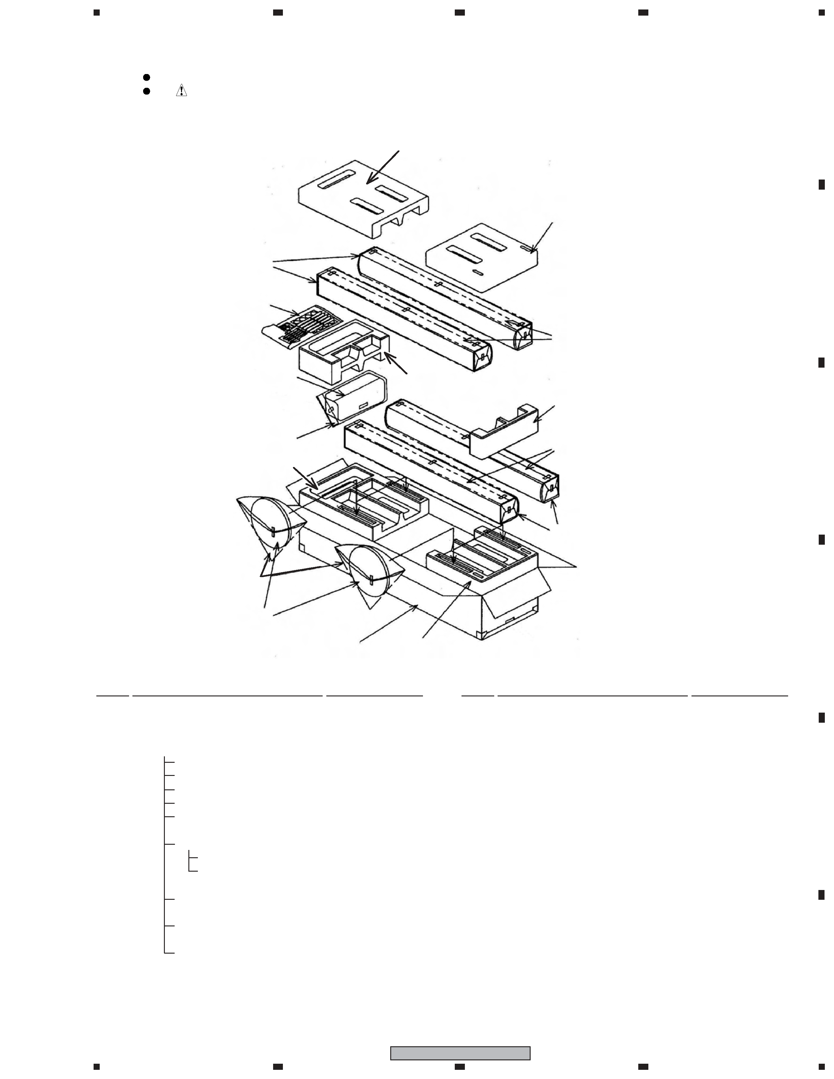
Rear
Front
Stem
(the bottom of cabinet)
Speaker Stand Base
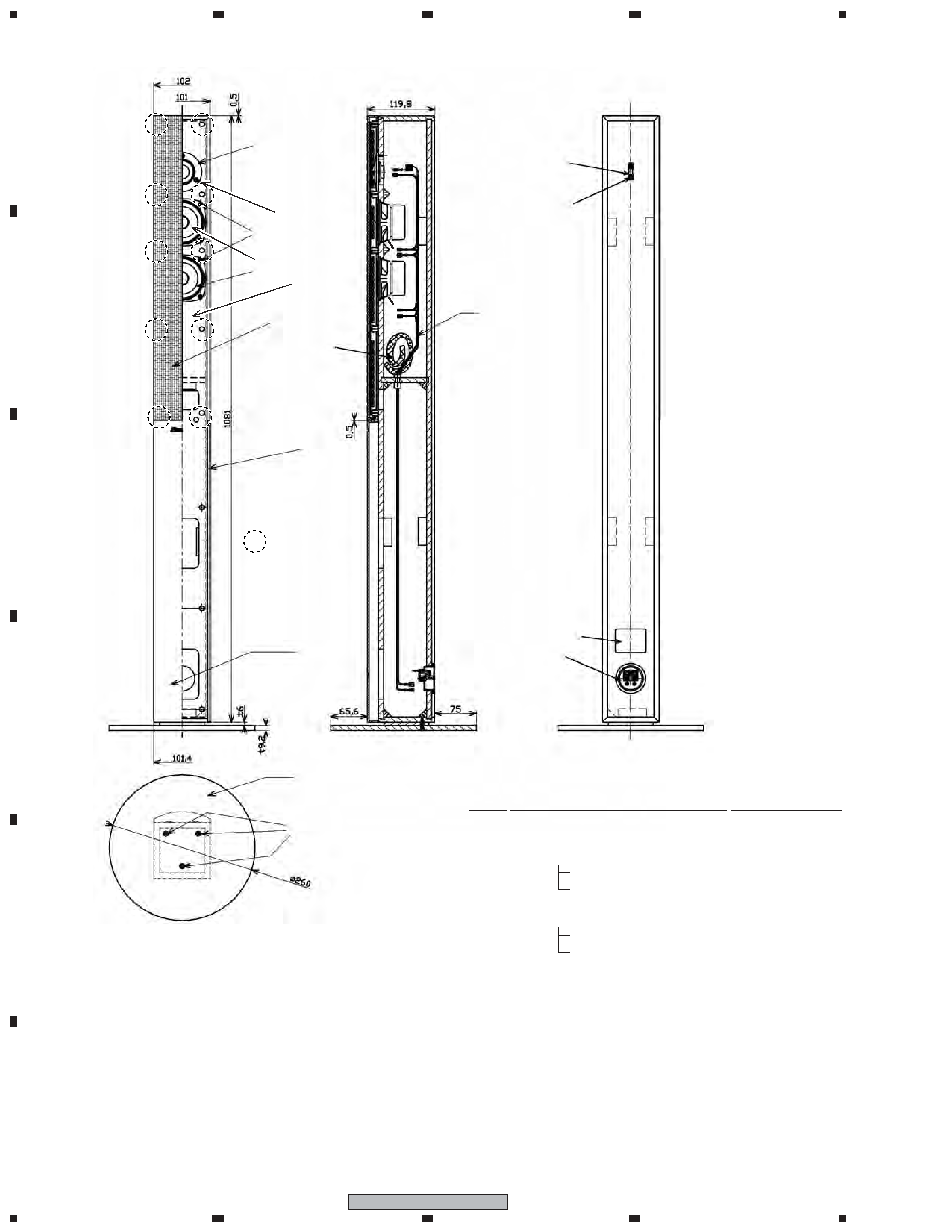
GRILLE
The grille is attached to the cabinet by its bosses applied with
adhesive. To detach it, pry it open by inserting a flat blade
screwdriver into lower right and lower left slot. To attach it,
apply adhesive to the holes on the baffle. Then press it to the
baffle.
CAUTION
There are 10 bosses for press-fitting at the grille. To detach the
grille, remove in order from lower bosses. (Refer to the figure
in page 4.) In order not to damage the bosses, don't remove it
forcibly. Pry it open little by little. Be sure to insert a flat blade
screwdriver from just beside of its bosses.
WOOFER
The woofer is attached to the baffle by 4 external screws.
To detach it, unfasten those screws. To detach it, first remove
the grille. Then remove the screws. When attaching it, face its
terminal downward.
TWEETER
The tweeter is attached to the baffle by 3 external screws. To
detach it, unfasten those screws. To detach it, first remove the
grille. Then remove the screws. When attaching it, face its ter-
minal leftward and rightward.
COSMETIC PANEL
The cosmetic panel is attached to the baffle by its bosses. To
detach it, pry it open by inserting a flat blade screwdriver into
lower slot. To detach it, first remove the speaker stand base and
grille. Then remove the cosmetic panel. When attaching it, fit
the boss into the hole on the baffle.
1. REASSEMBLY AND DISASSEMBLY PRECAUTIONS
1.1
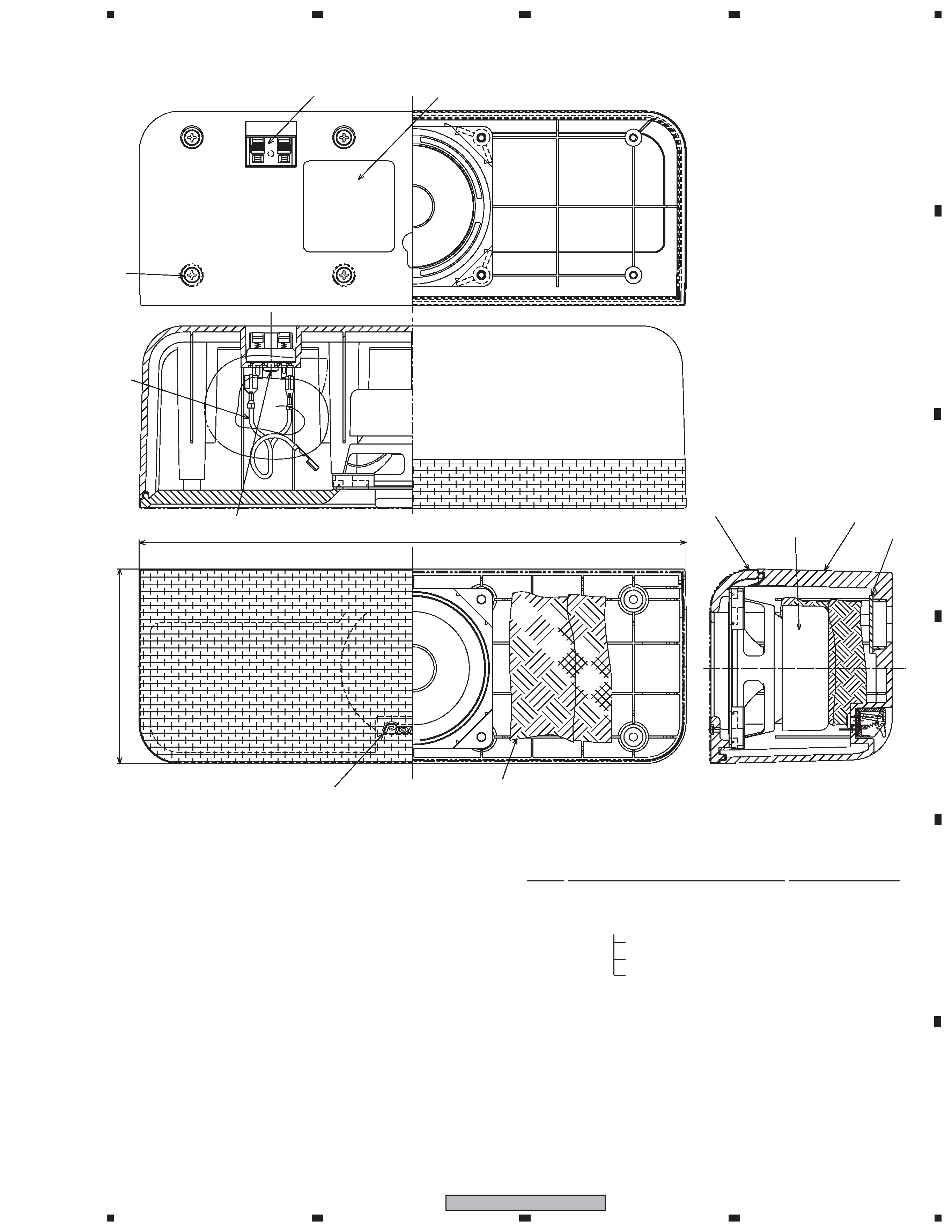
FRONT, SURROUND SPEAKER
GRILLE
The grille assy is attached to the cabinet by 8 external screws.
To detach it ,unfasten those screws.
SPEAKER UNIT
The speaker unit, together with the grille assy, is attached to the
cabinet by 4 external screws. To detach it, first remove the
grille assy. Next remove the cabinet. Then remove the cable.
When attaching it, face its terminal toward the input terminal.
1.2
CENTER SPEAKER
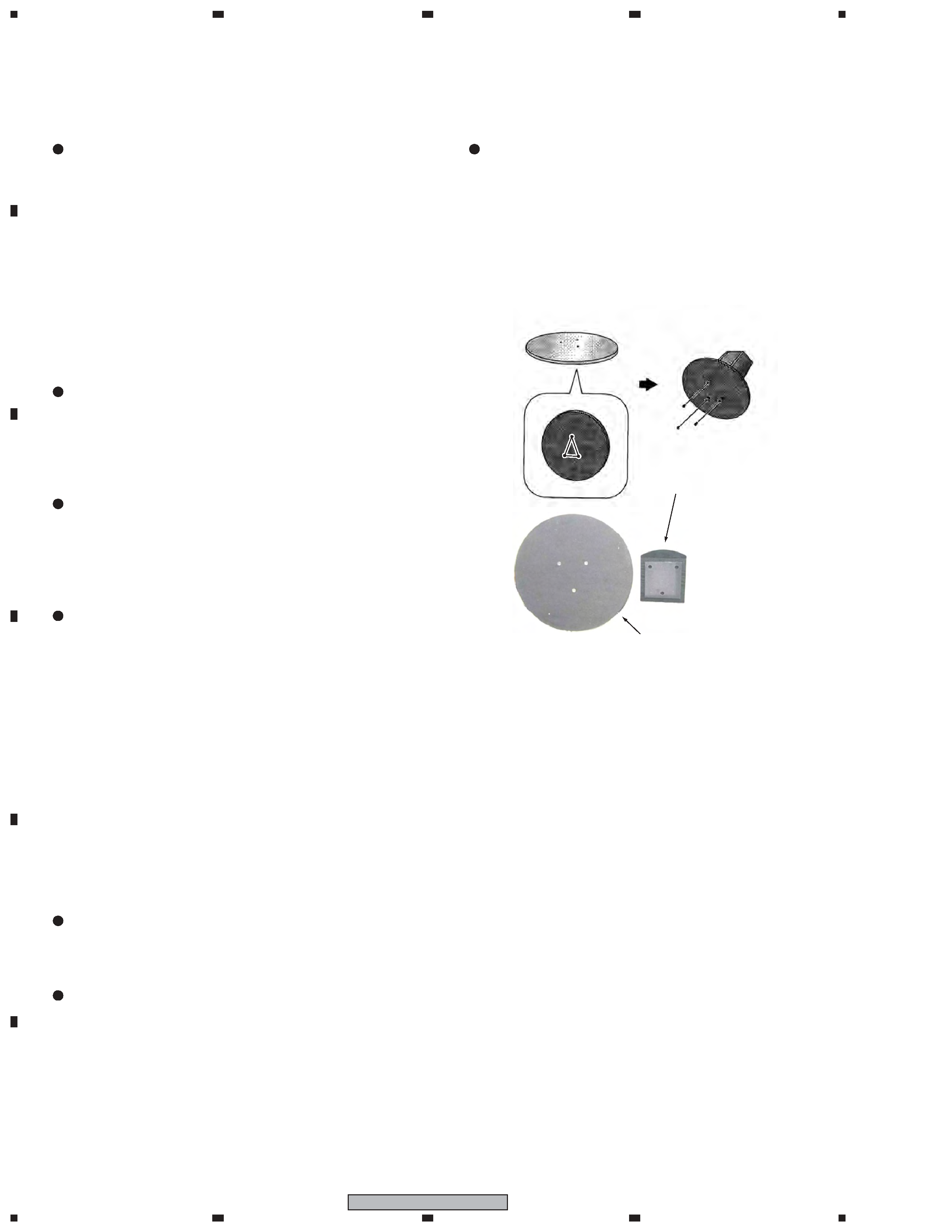
SPEAKER STAND BASES
The speaker stand base is attached to the bottom of cabinet by 3
external screws. To detach it, unfasten those screws.Attach the
speaker stand bases to the stems using the screws provided.
Once you have aligned the stem and base, secure with the small
screws at the points shown below. Note that the speaker should
face in the direction of the base of the isosceles triangle (out-
lined below).