ORDER NO.
PIONEER ELECTRONIC CORPORATION 4-1, Meguro 1-Chome, Meguro-ku, Tokyo 153-8654, Japan
PIONEER ELECTRONICS SERVICE, INC. P.O. Box 1760, Long Beach, CA 90801-1760, U.S.A.
PIONEER ELECTRONIC (EUROPE) N.V. Haven 1087, Keetberglaan 1, 9120 Melsele, Belgium
PIONEER ELECTRONICS ASIACENTRE PTE. LTD. 253 Alexandra Road, #04-01, Singapore 159936
PIONEER ELECTRONIC CORPORATION 1999
FILE-TYPE COMPACT DISC PLAYER
RRV2105
TZZR FEB. 1999 Printed in Japan
PD-F1007
THIS MANUAL IS APPLICABLE TO THE FOLLOWING MODEL(S) AND TYPE(S).
Type
Model
PD-F1007
Power Requirement
Remarks
MY
AC220-230V
KEYBORD
INPUT
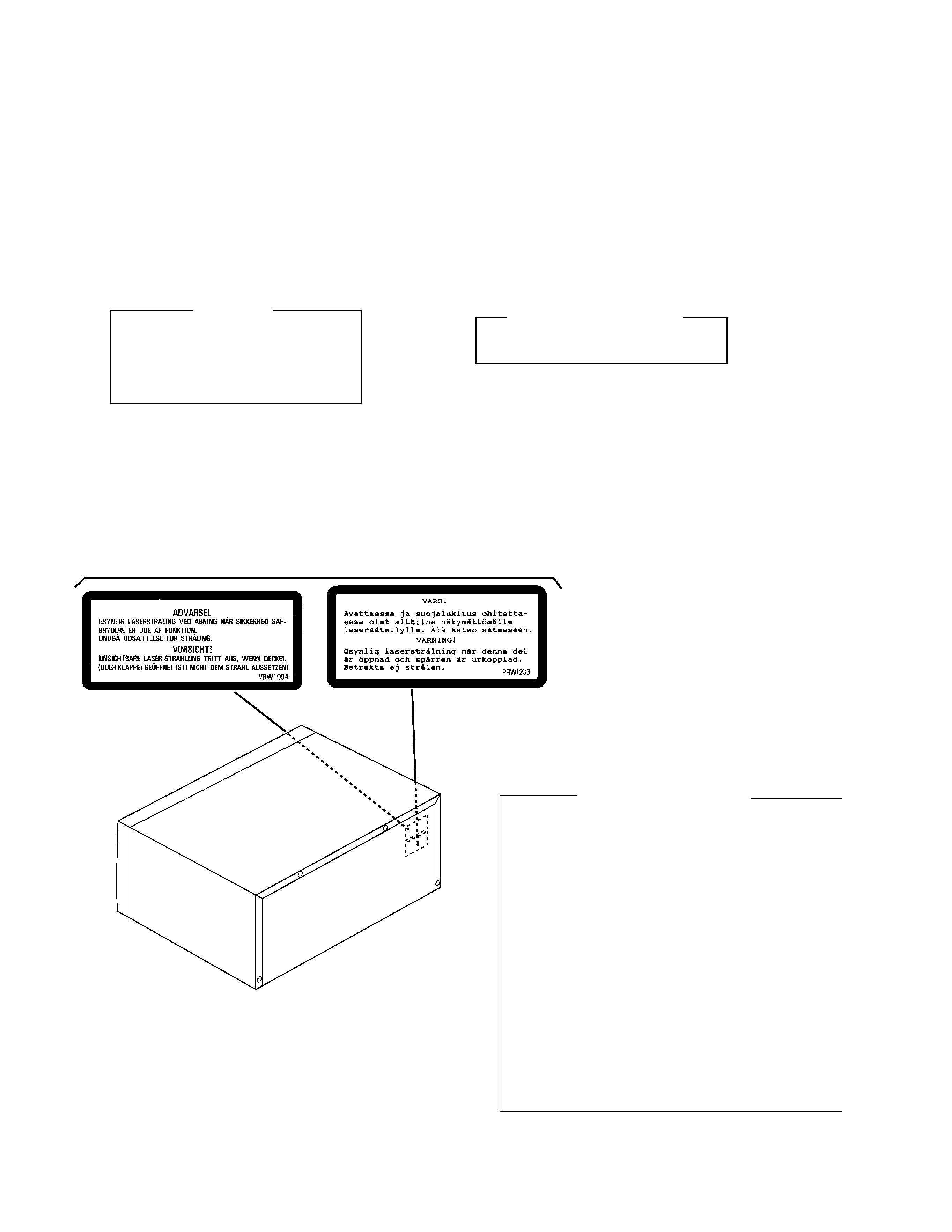
1. SAFETY INFORMATION .................................... 2
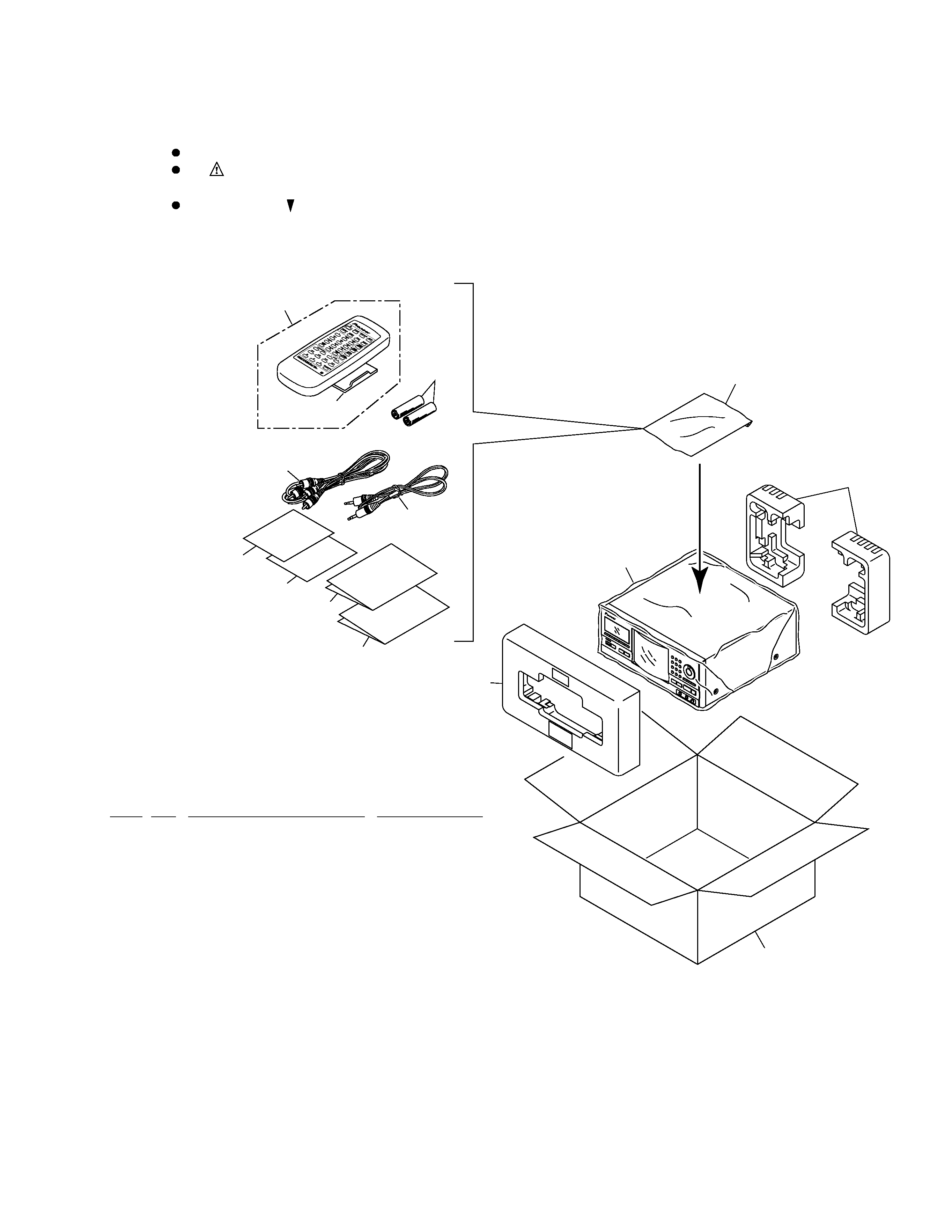
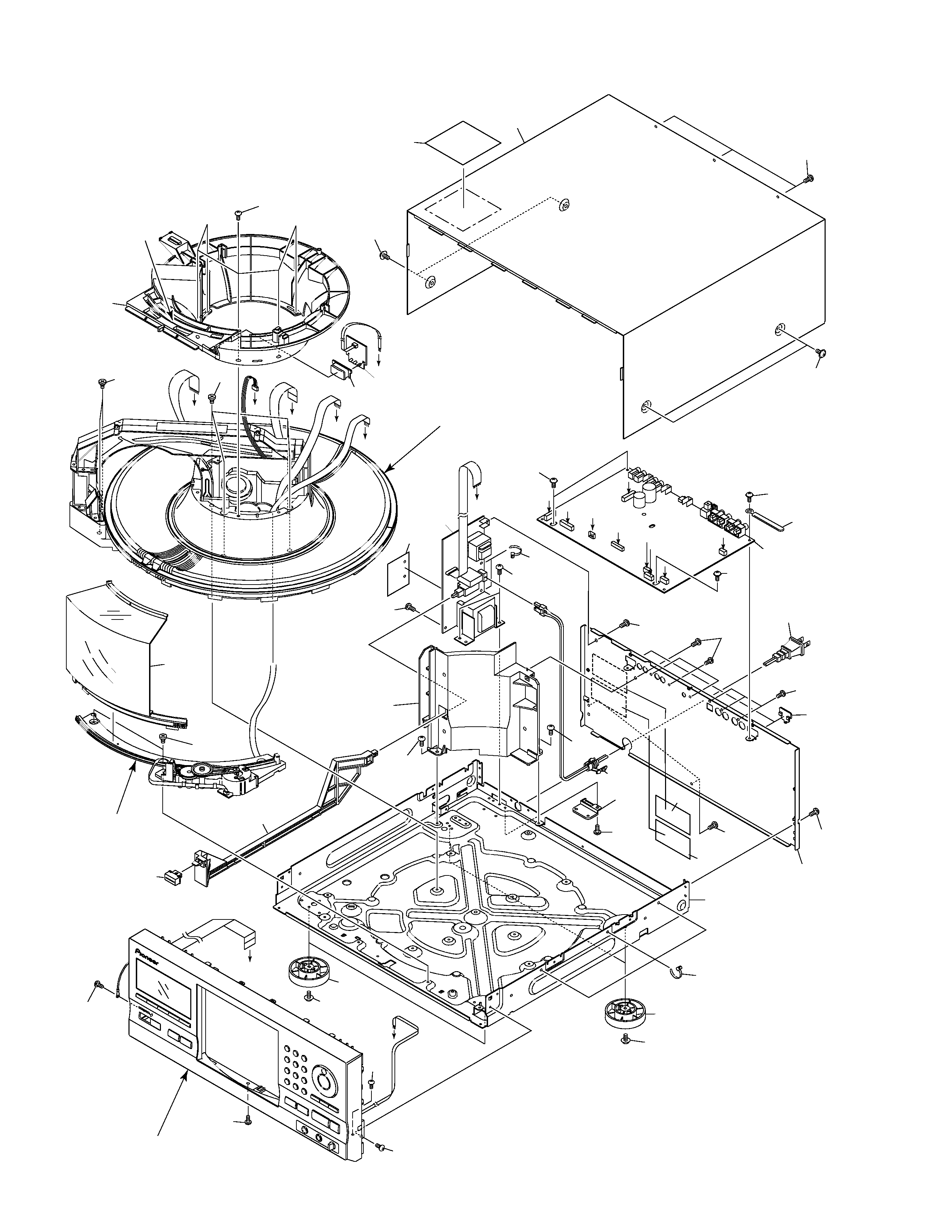
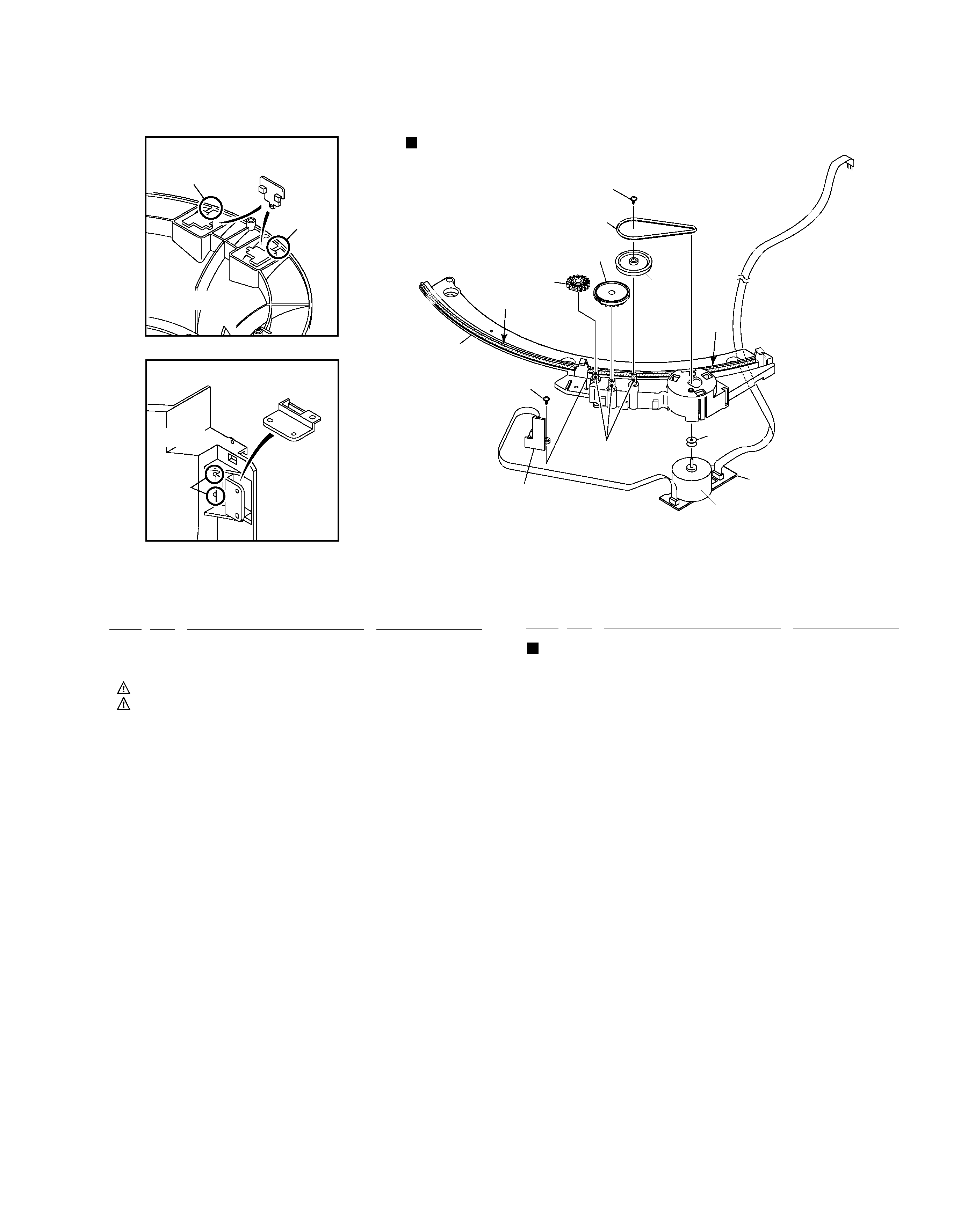
2. EXPLODED VIEWS AND PARTS LIST ............. 3
3. SCHEMATIC DIAGRAM ................................... 10
4. PCB CONNECTION DIAGRAM ....................... 22
5. PCB PARTS LIST ............................................. 30
6. ADJUSTMENT .................................................. 34
7. GENERAL INFORMATION .............................. 44
7.1 PARTS ....................................................... 44
7.1.1 IC ....................................................... 44
7.1.2 DISPLAY ........................................... 47
CONTENTS
7.2 DIAGNOSIS ................................................ 48
7.2.1 DISASSEMBLY ................................. 48
7.2.2 ERROR CCHECK DISPLAY ............. 51
7.2.3 EXPLANATION OF DISC
DETECTION ...................................... 52
7.3 BLOCK DIAGRAM ...................................... 54
8. PANEL FACILITIES AND SPECIFICATIONS
....................................................... 55