ORDER NO.
PIONEER CORPORATION 4-1, Meguro 1-chome, Meguro-ku, Tokyo 153-8654, Japan
PIONEER ELECTRONICS (USA) INC. P.O. Box 1760, Long Beach, CA 90801-1760, U.S.A.
PIONEER EUROPE NV Haven 1087, Keetberglaan 1, 9120 Melsele, Belgium
PIONEER ELECTRONICS ASIACENTRE PTE. LTD. 253 Alexandra Road, #04-01, Singapore 159936
PIONEER CORPORATION 2007
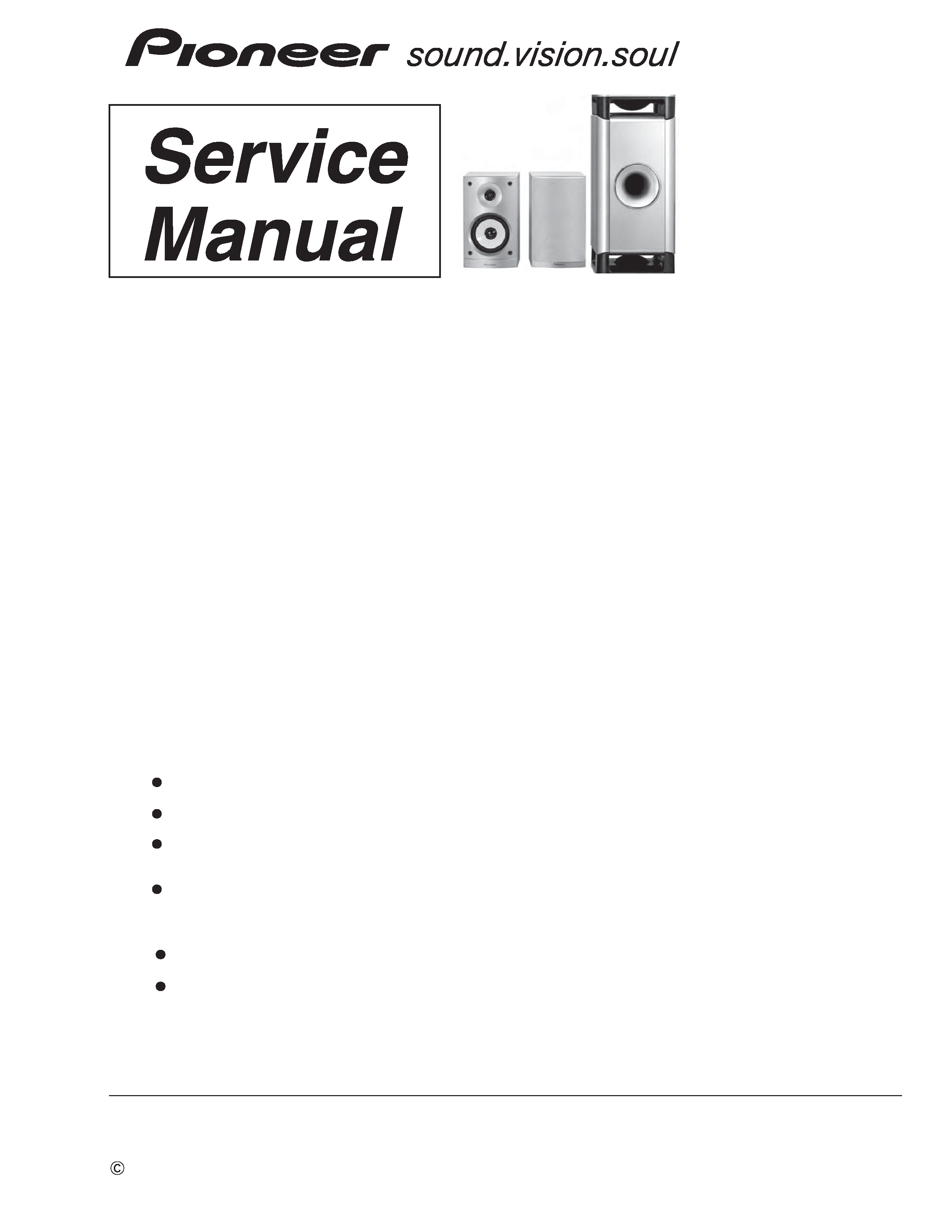
S-CX303
RRV3652
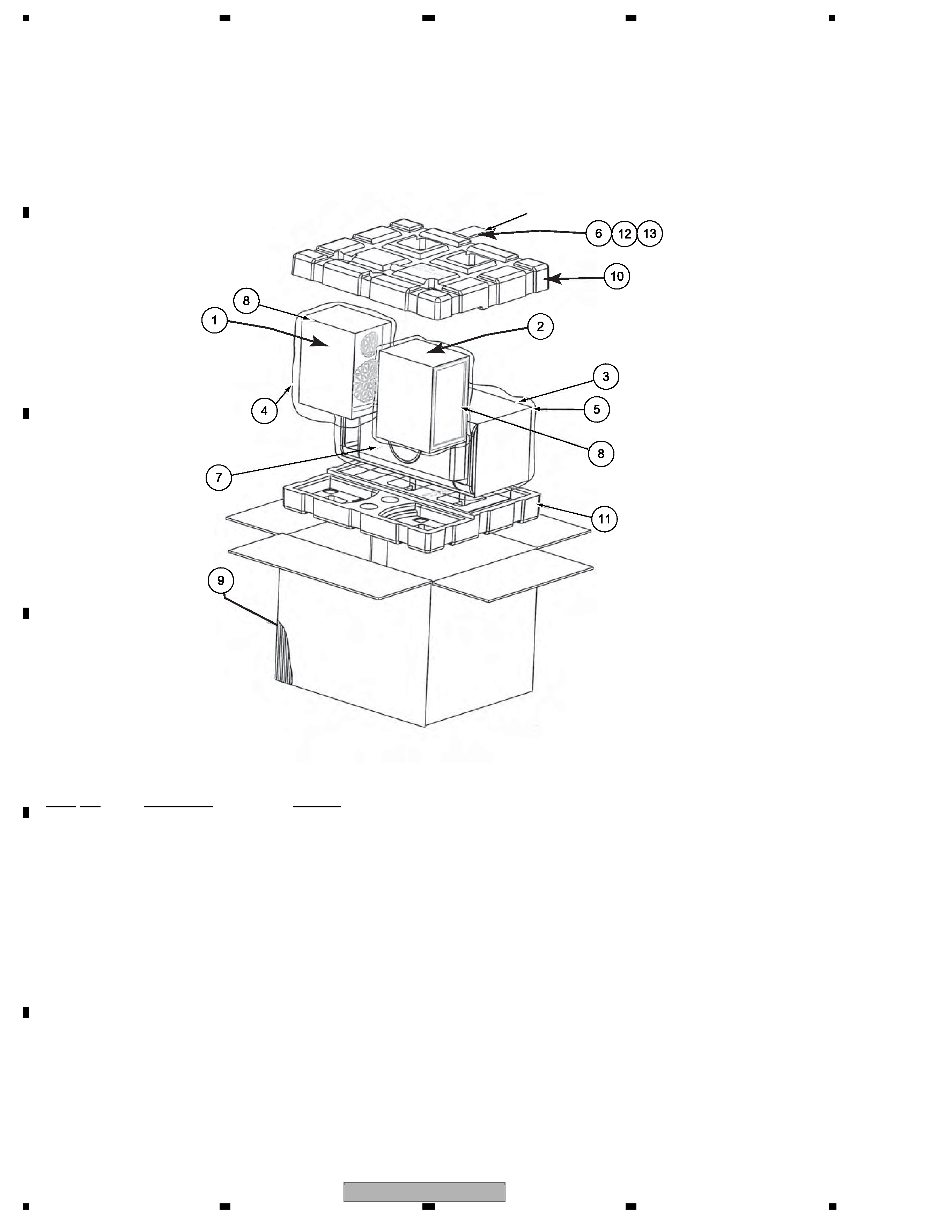
SPEAKER SYSTEM
S-CX303
XJM/E
1. REASSEMBLY AND DISASSEMBLY PRECAUTIONS
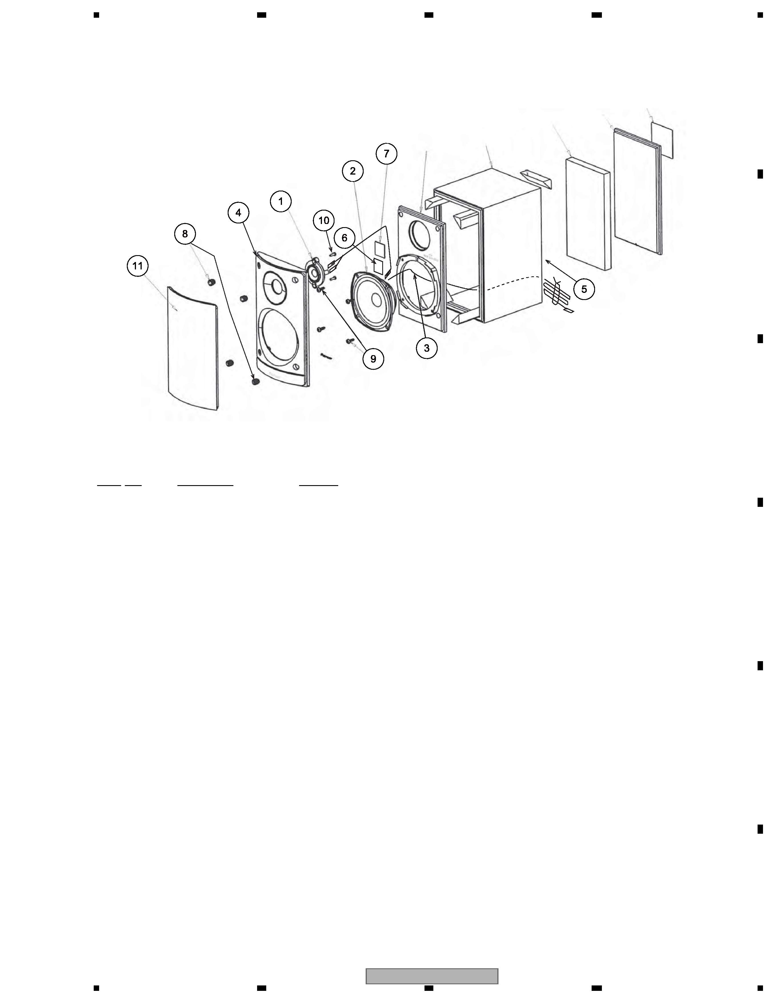
1.1 FRONT SPEAKER
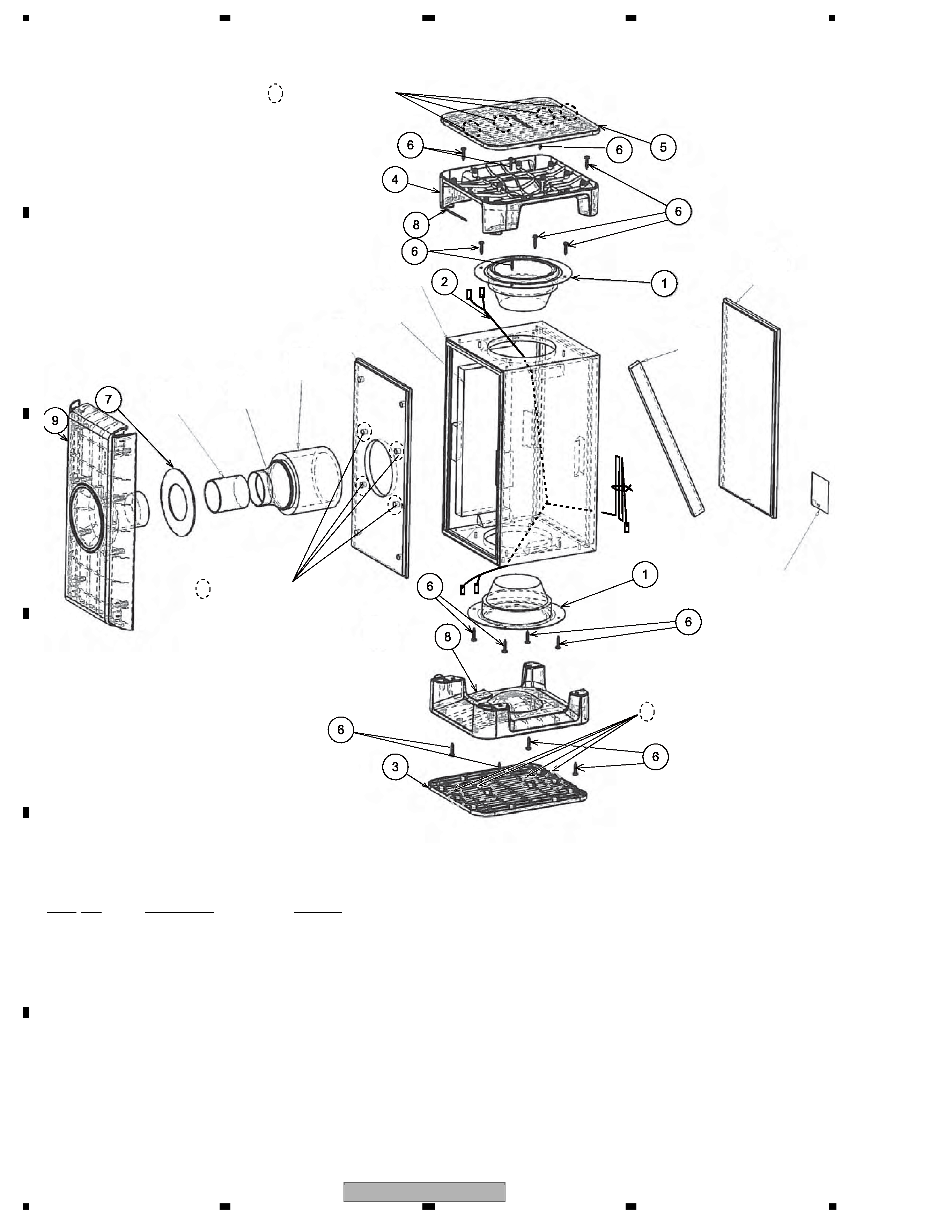
1.2 SUBWOOFER
The base cover is attached to the bass by press fitting.
To detach it, pry it open by inserting a flat blade screw driver into back side slot.
The base is attached to the cabinet by 4 external screws.
When detatch it, first remove the base cover. Next unfasten those screws.
The speaker unit is attached to the cabinet board by 4 external screws. To detach it, unfasten those screws.
The grille is attached to the cosmetic baffle by 4 catches.
Detach by pulling it toward you.
The cosmetic baffle is attached to the baffle by press fitting.
To detach it, pry it open by inserting a flat blade screwdriver into lower side slot.
The woofer is attached to the baffle by 2 external screws.
The tweeter is attached to the cosmetic baffle by 4 internal screws.
To detach the speaker unit, first remove the cosmetic baffle. Next unfasten those screws. Then remove the connecting cord .
When attaching the woofer, face its terminal toward the upward.
T-ZZR SEPT. 2007 Printed in Japan