ORDER NO.
PIONEER ELECTRONIC CORPORATION 4-1, Meguro 1-Chome, Meguro-ku, Tokyo 153-8654, Japan
PIONEER ELECTRONICS SERVICE, INC. P.O. Box 1760, Long Beach, CA 90801-1760, U.S.A.
PIONEER ELECTRONIC (EUROPE) N.V. Haven 1087, Keetberglaan 1, 9120 Melsele, Belgium
PIONEER ELECTRONICS ASIACENTRE PTE. LTD. 253 Alexandra Road, #04-01, Singapore 159936
PIONEER ELECTRONIC CORPORATION 1998
RRV2069
T-ZZW DEC. 1998 Printed in Japan
This product is component of system.
For the operating instructions, refer to the service manual RRV2064 for XR-A660.
SPEAKER SYSTEM
S-A660
XC
FOR PRECAUTION OF
REASSEMBLY AND DISASSEMBLY
65S
This service manual is intended for qualified service technicians; it is not meant for the
casual do-it-yourselfer. Qualified technicians have the necessary test equipment and
tools, and have been trained to properly and safely repair complex products such as
those covered by this manual.
Improperly performed repairs can adversely affect the safety and reliability
of the product and may void the warranty. If you are not qualified to perform the repair
of this product properly and safely, you should not risk trying to do so and refer the
repair to a qualified service technician.
WARNING
Lead in solder in this product is listed by the California Health and Welfare agency as
a known reproductive toxicant which may cause birth defects or other reproductive
harm (California Health & Safety Code, Section 25249.5).
When servicing or handling circuit boards and other components which contain lead in
solder, avoid unprotected skin contact with the solder. Also, when soldering do not in
hale any inhale any smoke or fumes produced.
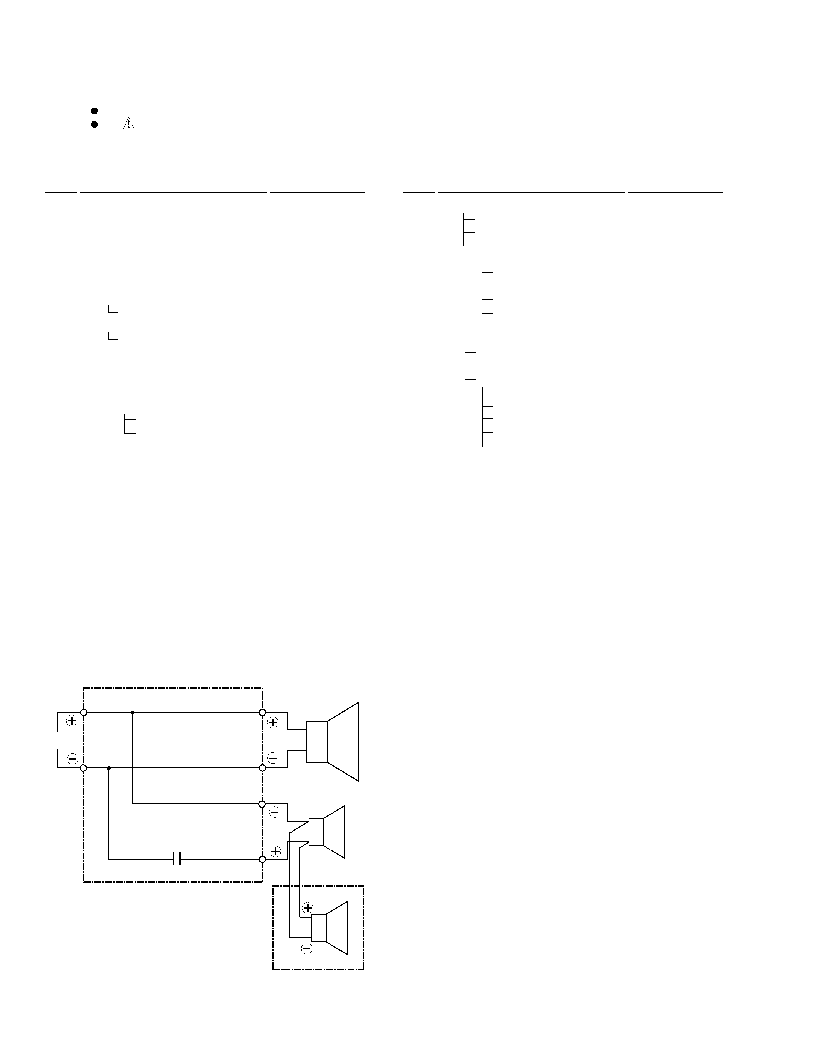
The woofer is attached to the cosmetic baffle assy together
with the woofer ring assy by 4 internal screws. To detach the
woofer (woofer ring assy), loosen these screws. To attach the
woofer ring assy, fit the boss of the woofer ring to the hole of
the cosmetic baffle assy. To attach the woofer, face its terminal
downward, and fit the portion of the notch and hole of the
frame to the bank and hole of the cosmetic baffle assy. To at-
tach the woofer ring assy and woofer, replace it on the cosmetic
baffle assy correctly and secure with 4 screws.
The mid-range is attached to the cosmetic baffle assy by 2 in-
ternal screws. To detach the mid-range, loosen these screws.
Then carefully disconnect the wires of the tweeter mounted on
the cosmetic baffle assy by adhesion. To attach the mid-range,
replace it on the cosmetic baffle assy correctly and secure with
2 screws.
The network assy is attached to the back board of the cabinet
by press-fitting. To detach the network assy, strike the cord-
stopper of the network assy with a hammer from inside of the
cabinet. To attach the network assy, replace it on the back
board of the cabinet correctly by press-fitting.
When exchange the tweeter, do it with the cosmetic baffle
assy.
The cosmetic baffle assy is attached to the cabinet by 4 external
screws. To detach the cosmetic baffle assy, loosen these
screws. Then carefully disconnect the wires of the woofer and
mid-range mounted on the cosmetic baffle assy. To attach the
cosmetic baffle assy, replace it on the cabinet correctly and se-
cure with 4 screws.