ORDER NO.
PIONEER CORPORATION 4-1, Meguro 1-chome, Meguro-ku, Tokyo 153-8654, Japan
PIONEER ELECTRONICS SERVICE, INC. P.O. Box 1760, Long Beach, CA 90801-1760, U.S.A.
PIONEER ELECTRONIC (EUROPE) N.V. Haven 1087, Keetberglaan 1, 9120 Melsele, Belgium
PIONEER ELECTRONICS ASIACENTRE PTE. LTD. 253 Alexandra Road, #04-01, Singapore 159936
PIONEER CORPORATION 1999
RRV2209
T-ZZM SEPT. 1999 Printed in Japan
SPEAKER SYSTEM
S-A370
XTL/NC
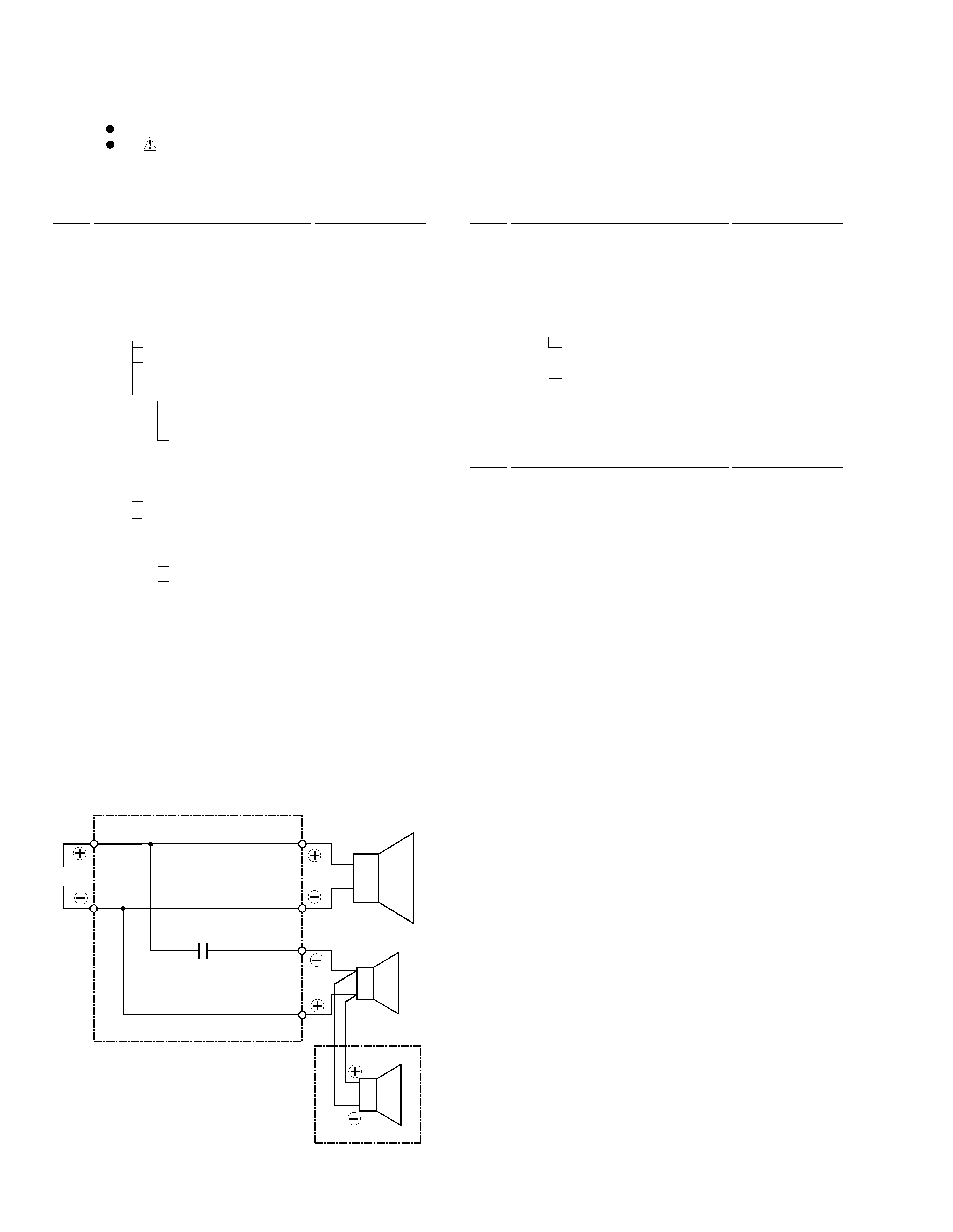
FOR PRECAUTION OF
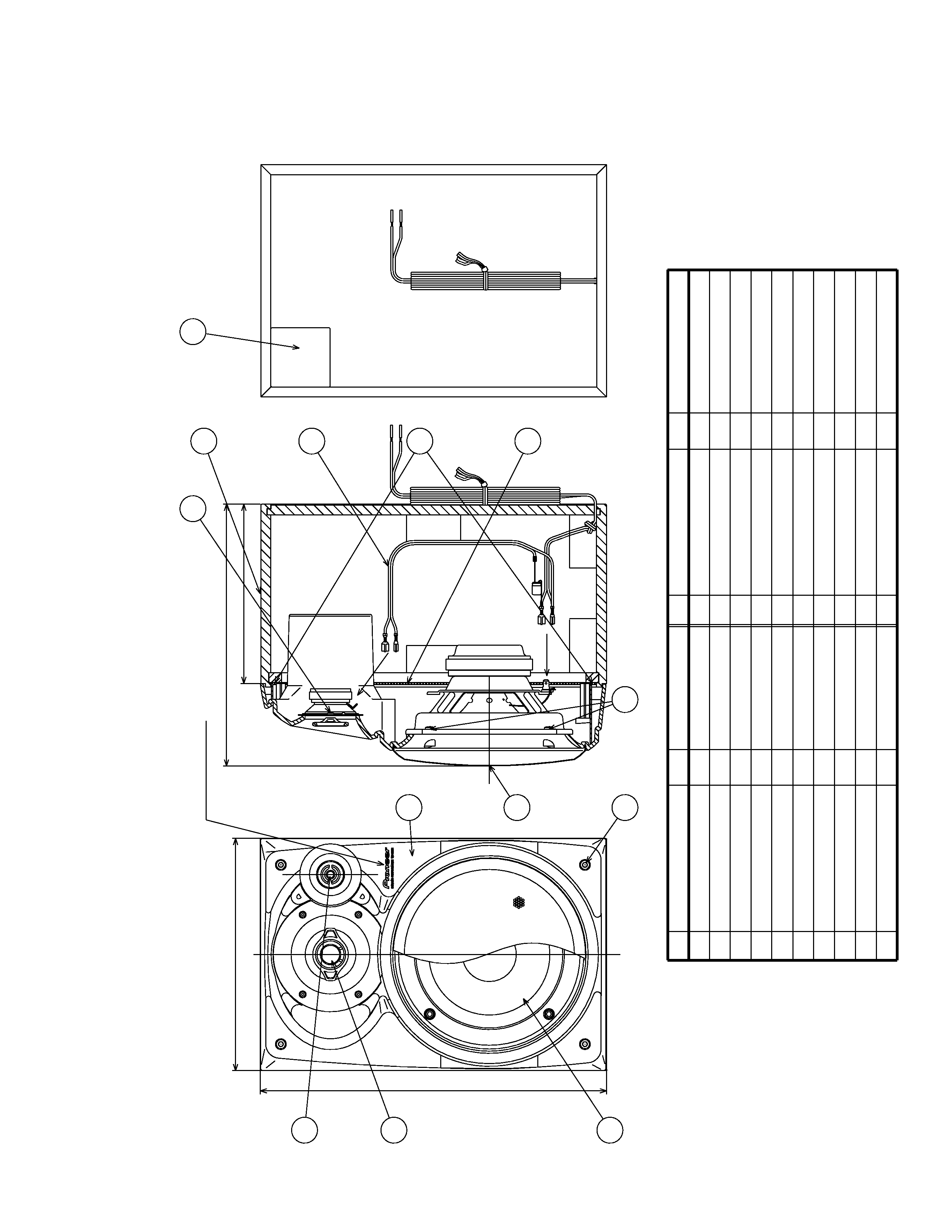
REASSEMBLY AND DISASSEMBLY
The cosmetic baffle assy is attached to the cabinet by 4 external
hexagon socket screws. To detach the cosmetic baffle assy,
loosen these screws by the hexagon screw driver. Then care-
fully disconnect the wires of the woofer and mid-range
mounted on the cosmetic baffle assy. To attach the cosmetic
baffle assy, replace it on the cabinet correctly and secure with 4
screws.
The woofer is attached to the cosmetic baffle assy by 4 internal
screws. To detach it, unfasten these screws. When attaching it,
face its terminal downward.
The mid-range is attached to the cosmetic baffle assy by 2 inter-
nal screws. To detach the mid-range, loosen these screws. Then
carefully disconnect the wires of the tweeter mounted on the
cosmetic baffle assy by adhesion. To attach the mid-range, re-
place it on the cosmetic baffle assy correctly and secure with 2
screws.
When exchange the tweeter, do it with the cosmetic baffle assy.
This product is component of system.
System
Service Manual
Remarks
RRV2215
RRV2209
Component
X-A370
XR-A370
S-A370
STEREO CD CASSETTE DECK RECIEVER
SPEAKER SYSTEM
This service manual