2
TZ-F700
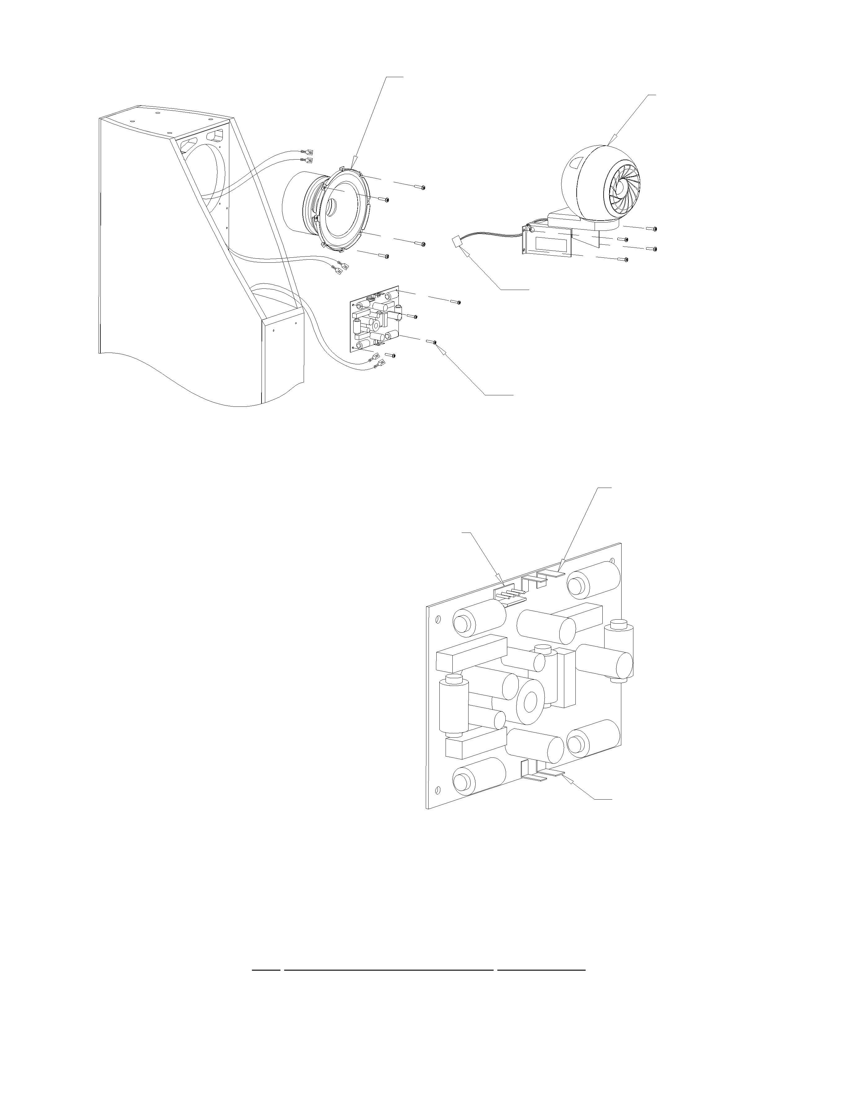
1. WOOFER REPLACEMENT
1.1 REMOVAL
1.
Support loudspeaker on it's side.
2.
Remover 8 screws.
3.
Remove bottom and 8 standoffs.
4.
Carefully pull woofer forward, and disconnect blue
and blue/black cables.
1.2 REFITTING
1.
With loudspeaker on it's side, reconnect blue and blue/
black cables
2.
Position the B-300 woofer in the base assembly, taking care
to align the 8 holes in the woofer with the bosses in the base
assembly.
3.
One at a time, insert screw P/N 261463-A through hole
in the bottom, through stanoff, and through woofer screw
hole and engage into the boss with 2 or 3 turns. Note
correct orientation of standoff, and make sure that the
mounting holes for the spiked heel are correctly oriented.
4 . Once all 8 screws 4 are engaged, tighten each in a
diametrically opposed torque pattern to a torque of 12.0 lb-
in.
2. AMPLIFIER
2.1 REMOVAL
1.
Remove the 6 screws P/N 261478-A
2.
Pull the amplifier forward approx. 3 inches to expose the 4
wires. (clear, clear/black, red, black)
3.
Disconnect these wires from the amplifier.
4.
Continue to pull the amplifier forward, and disconnect the
molex connector.
5.
Finally, disconnect the blue and blue/black wires.
6.
Remove the amplifier.
2.2 REFITTING
1.
REFITTING is a removal of the removal procedure. All
connectors are polarized.
2.
When pushing amplifiers back into the cabinet, take care to
dress cables so that they are not trapped or stretched as the
amplifier is reinserted.
.3. Replace 6 screws with a torque setting of 6.0 lb-in.
3. BASE ASSEMBLY
3.1 REMOVAL
1.
First remove and disconnect the amplifier as described in
section 2.
2.
Next, remove the woofer as described in section 1.
3.
Remove the 10 screws P/N 217609.
4.
Pull the base assembly away from the cabinet, taking care
not to damage the gasket sealing strip P/N 260564.
3.2 REFITTING
1 . Check the sealing strip P/N 260564 is continuous. If not,
replace.
2.
Carefully realign 10 holes in blue assembly with holes in
the cabinet.
3.
Make sure that level control is oriented the front of the
loudspeaker; and that no cables are trapped between the
base and the cabinet.
4.
Replace 10 screws, and tighten in an opposed torque
pattern to a setting of 12.0 lb-in.
5. Replace woofer as described in section 1, and amplifier as
in section 2.
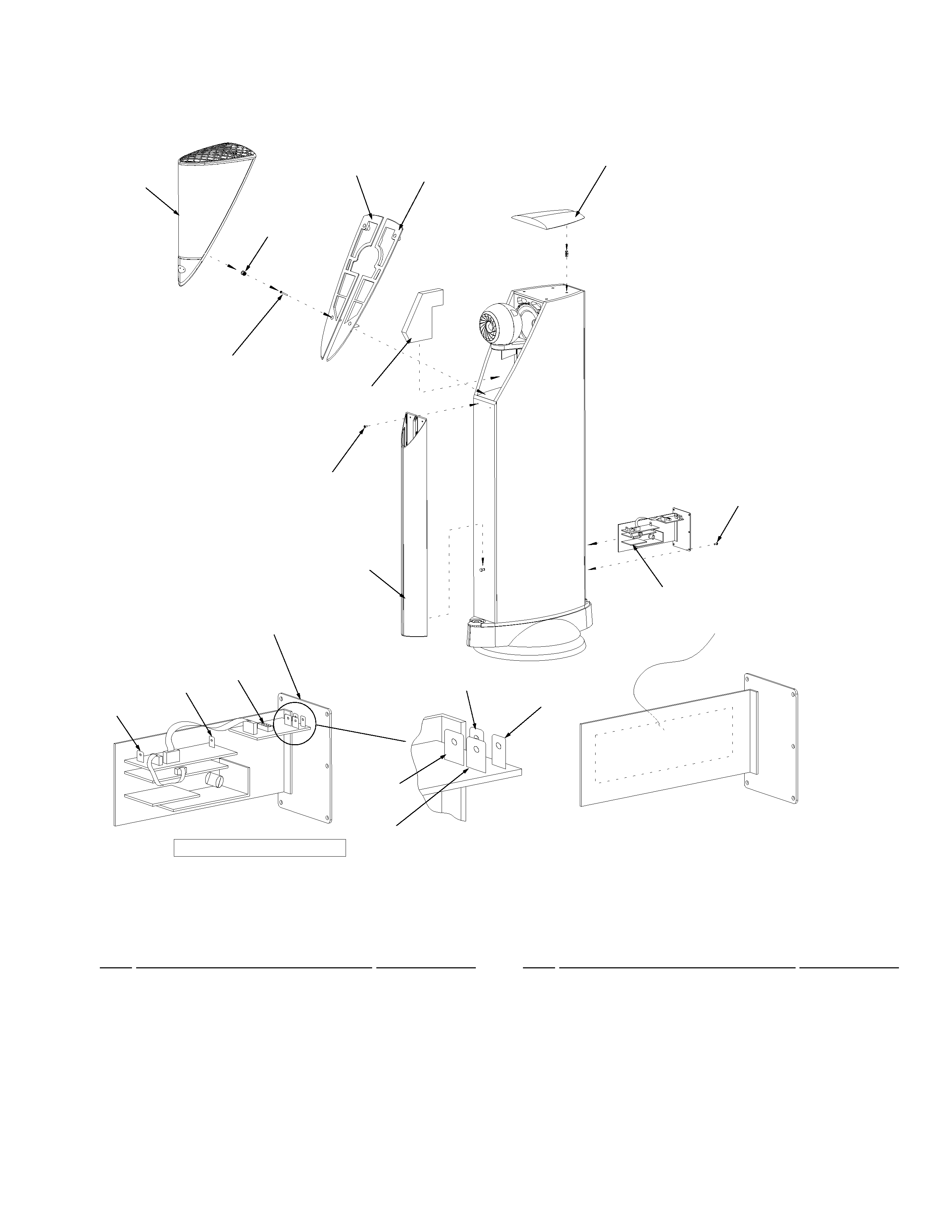
4. GRILLE
4.1 REMOVAL
1.
The grille is attached with four catch cups. Carefully pull
the grille assemble forward. DO NOT hold the grille by the
curved side. ONLY hold the grill by it's and it's perimeter.
4.2 REFITTING
1.
Carefully realign the grille page with the catch cups
Push the grille carefully into place. DO NOT push on the
curved sides. ONLY push on the top and perimeter.
5. SUB-BAFFLE
5.1 REMOVAL
1.
Remove the 4 catch cups by pulling forward.
2 . Remove the 4 screws revealed under the catch cups.
3.
Carefully lift the sub-baffle , away from the cabinet. It is
additionally held in place by a self-adhesive tape halfway
along the outer edge. This bond can be broken bY gently
pressing the baffle away from the cabinet using your finger.
4.
Gently flex the sub-baffle in order to twist it around the
IRIS subassembly.
5.2 REFITTING
1.
If necessary, replace the self adhesive tape on the sub-
baffle.
2.
Gently flex the sub-baffle and replace each half onto the
cabinet.
3.
Align the sub-baffles so that two halves match and meet in
the middle, then replace the 4 screws.
4.
Carefully turn the screws starting with the top screws first,
until you see the sub-baffle start to flex. Stop and back off
1/4 turn. Overtightening will cause the sub-baffles to bend
and not lay flat.
5.
Press down on the edge where the self adhesive tape is
located, to ensure a good bond
6.
Replace the 4 catch cups. Take care to avoid pulling the
grill cloth into the hole as you insert the cup.
6. IRIS ASSEMBLY
6.1 REMOVAL
1.
First, remove the sub-baffle as described in section 5.
2.
Remove the acoustic absorbent, 5 pieces.
3.
Disconnect the molex connector from the crossover 28 .
4.
Support the IRIS assembly and remove the 4 screws P/N
222016.
5.
Lift the IRIS assembly upwards and away from the cabinet.
6.
Take care when setting the IRIS assembly down that it dose
not roll forward onto the diaphragm surface.
6.2 REFITTING
1.
Refitting is a reversal of the procedure for removal.
2
Use a torque setting of 12.0 lb-in for replacing the screws.
When refitting the acoustic absorbent, take care to ensure
that it dose not contact the mid-bass drive unit.