2
PDR-F10
1. SAFETY INFORMATION
This service manual is intended for qualified service technicians ; it is not meant for the casual do-it-
yourselfer. Qualified technicians have the necessary test equipment and tools, and have been trained
to properly and safely repair complex products such as those covered by this manual.
Improperly performed repairs can adversely affect the safety and reliability of the product and may
void the warranty. If you are not qualified to perform the repair of this product properly and safely, you
should not risk trying to do so and refer the repair to a qualified service technician.
USYNLIG LASERSTRÅLING VED ÅBNING NÅR SIKKERHED SAF-
BRYDERE ER UDE AF FUNKTION.
UNDGÅ UDSÆTTELSE FOR STRÅLING
UNSICHTBARE LASER-STRAHLUNG TRITT AUS, WENN DECKEL
(ODER KLAPPE) GEÖFFNET IST! NICHT DEM STRAHL AUSSETZEN!
VRW1094
ADVARSEL
VORSICHT!
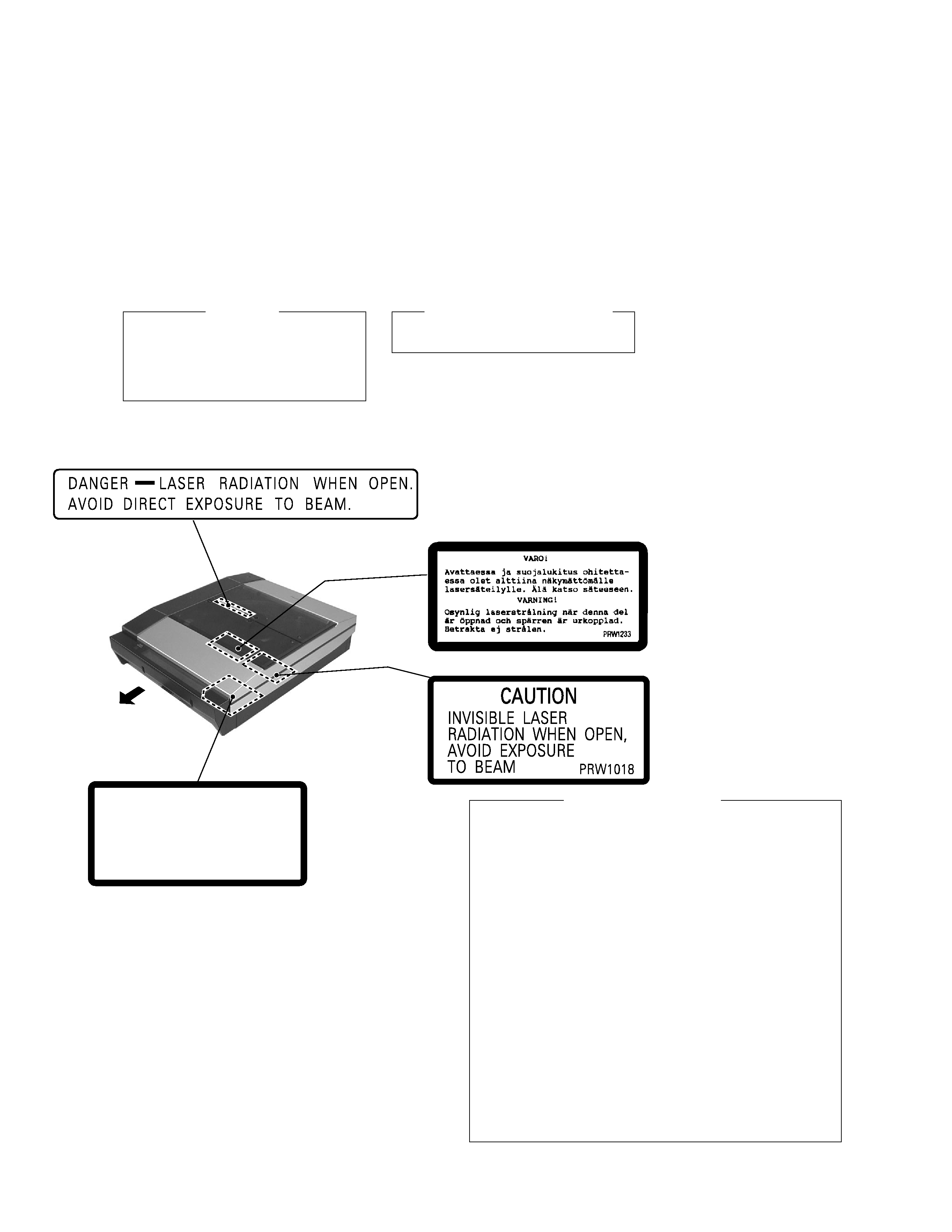
LABEL CHECK (ZVYXJ)
Put on Door Window RA
FRONT
IMPORTANT
THIS PIONEER APPARATUS CONTAINS
LASER OF CLASS 3b.
SERVICING OPERATION OF THE APPARATUS
SHOULD BE DONE BY A SPECIALLY
INSTRUCTED PERSON.
LASER DIODE CHARACTERISTICS
MAXIMUM OUTPUT POWER : 23 mW
WAVELENGTH : 778-787 nm
1. Laser Interlock Mechanism
The position of the switch (S5907) on the CD SW Assy for
detecting loading state is detected by the system micro-
processor, and the design prevents laser diode oscillation
when the switch (S5907) is not on CLOSE terminal side
(CDO/C signal is high level.).
Thus, the interlock will no longer function if the switch
(S5907) is deliberately set to CLOSE terminal side (low
level).
The interlock also does not function in the test mode
.
Laser diode oscillation will continue, if pin 1 of M51593FP
(IC101) on the CD-R CORE PCB ASSY mounted on the
CD-R PICKUP is connected to GND, or pin 19 is
connected to low level (ON), or else the terminals of Q101
are shorted to each other (fault condition).
2. When the DOOR WINDOW is removed, close viewing of
the objective lens with the naked eye will cause exposure
to a Class 3 laser beam.
Additional Laser Caution
Refer to page 44.