English
2
CHECKING THE ACCESSORIES
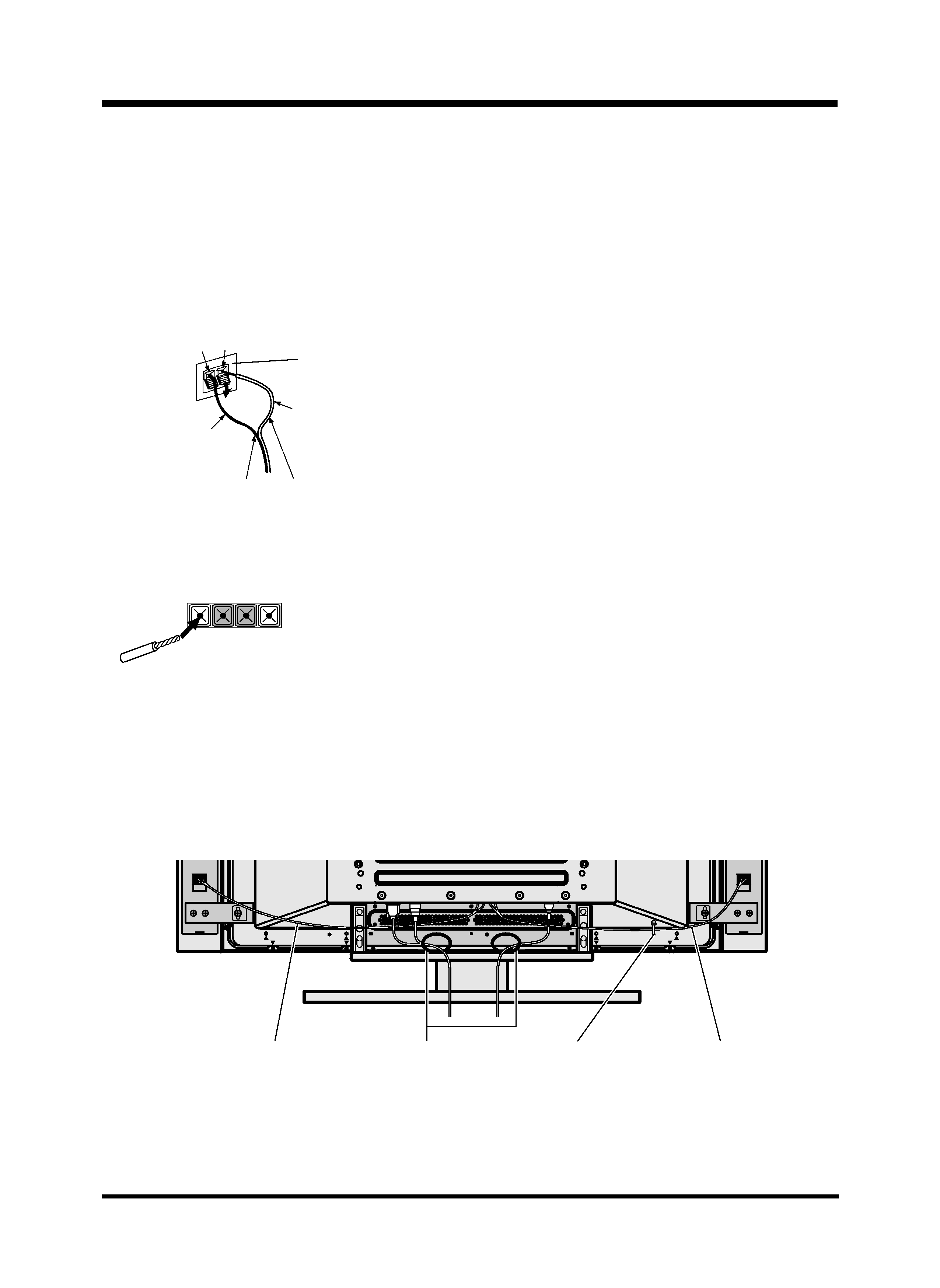
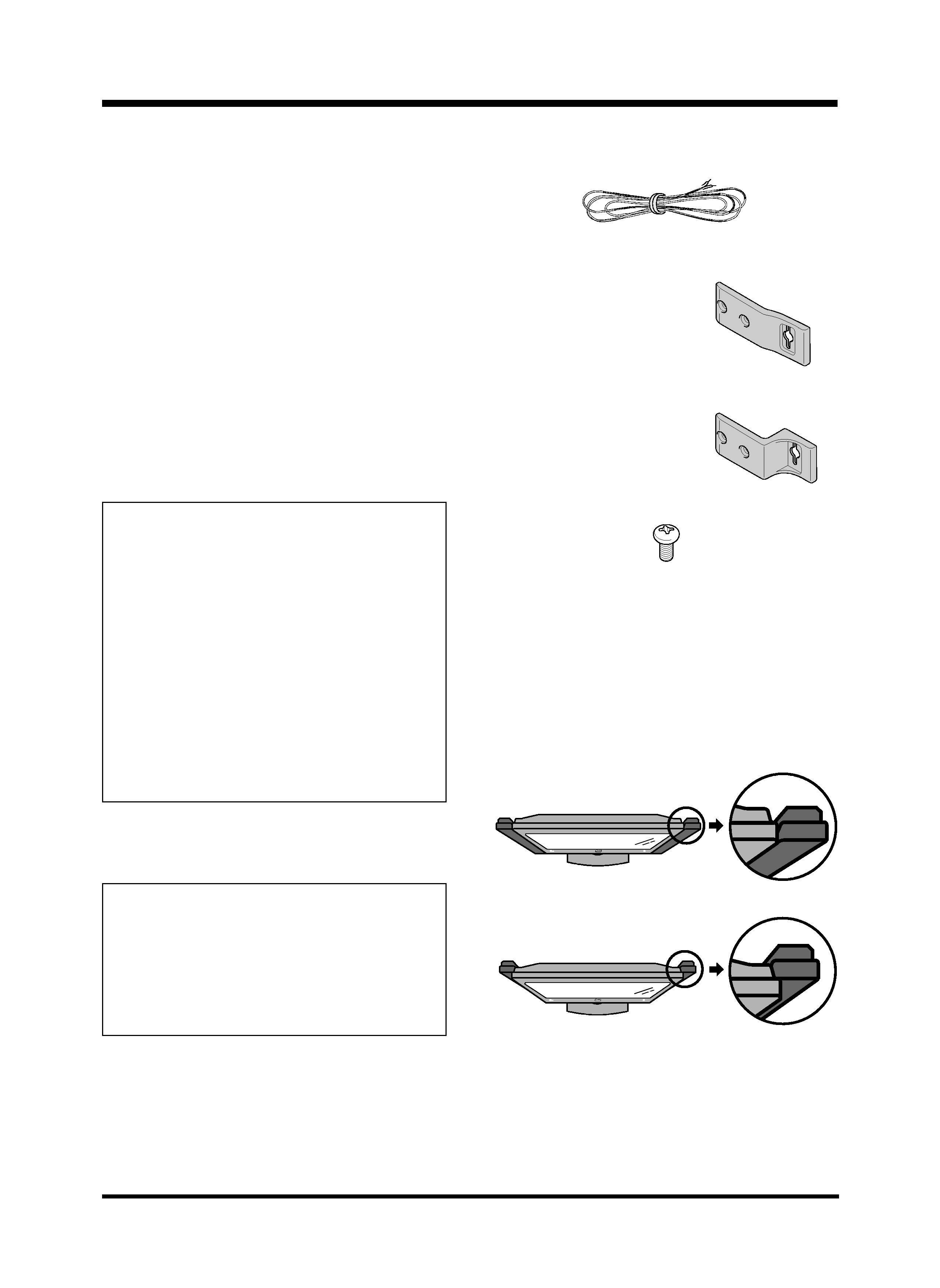
7 Speaker cable x 2
Thank you for buying this Pioneer product.
Please read through these operating instructions before
using your speaker system so you will know how to make
the most of its performance. After you have finished reading
the instructions, put them away in a safe place for future
reference.
BEFORE USE
÷ The nominal impedance of this speaker system is 8 ohms.
÷ In order to prevent damage to the speaker system
resulting from input overload, please observe the
following precautions:
÷ Do not supply power to the speaker system in
excess of the maximum permissable input. This
can result in damage or a possible fire hazard.
÷ When connecting or disconnecting pin-plugs, be
sure that amplifier power is OFF.
÷ When using a graphic equalizer to emphasize loud
sounds of a high frequency range, do not use
excessive amplifier volume.
÷ Do not force a low-powered amplifier to produce a
loud volume of sound (the amplifier's harmonic
distortion will be increased, and you may damage
the speaker).
÷ Please handle the speakers with sufficient care, as
the grille net and the cabinet can become damaged
or broken when they are subjected to strong external
impacts.
÷ Placing a CRT computer screen or CRT monitor near to
the speakers may result in interference or color distortion.
If this happens, distance the monitor from the speakers.
This product is designed for use with the PRO-910HD
Pioneer plasma display. For more information on
compatibility, please consult with your nearest Pioneer
authorized dealer or service center.
7 Operating Instructions
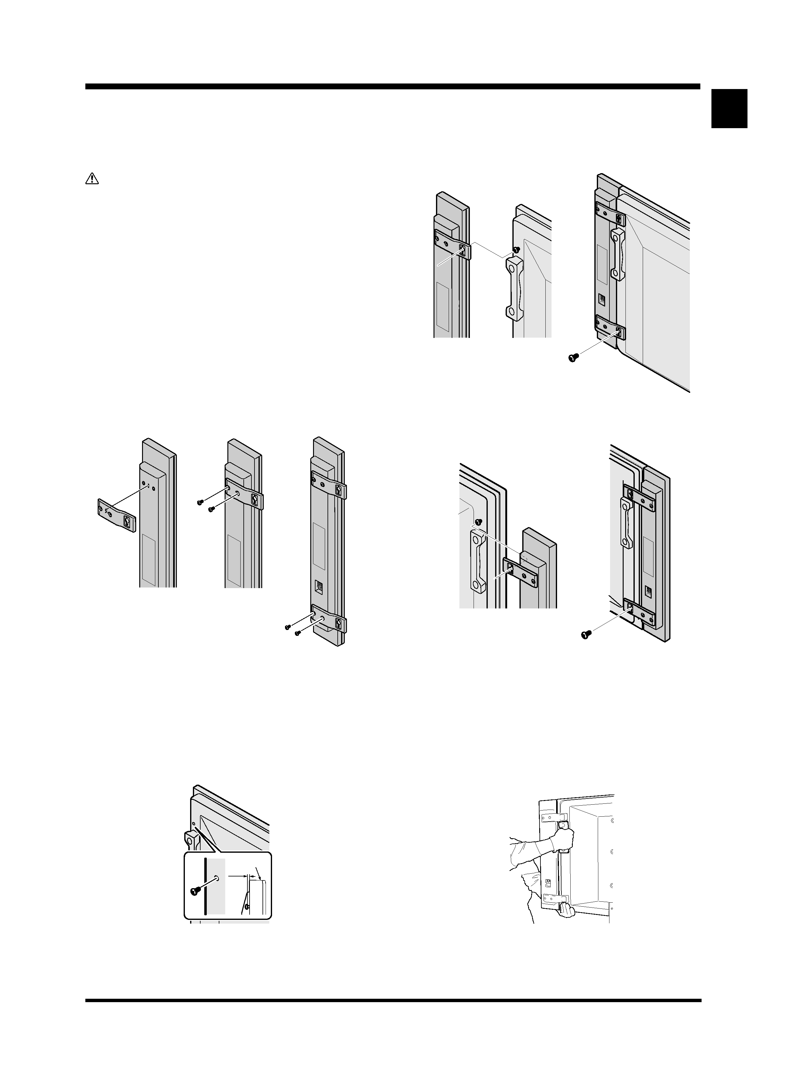
7 Speaker mounting fittings (Used when installing the
speakers flush with the display)
Holder for flush
mounting x 4
7 Speaker mounting fittings (Used when installing the
speakers set back from the display)
7 Speakers mounting screws
NOTE:
÷ Always use the accessory mounting fittings for
installation.
÷ When screws other than those enclosed as accessories
are used to install the speakers, the speakers may drop
off or accidents may be caused. Always use the screws
enclosed as accessories.
Notes on Installation Work:
This product is marketed assuming that it is installed by
qualified personnel with enough skill and competence.
Always have an installation specialist or your dealer install
and set up the product.
PIONEER cannot assume liabilities for damage caused
by mistake in installation or mounting, misuse,
modification or a natural disaster.
CAUTION
x 12
The customer can select whether to install the speakers flush
with the screen or set back slightly.
Flush
Set back
See the description below for details of the installation.
NOTE:
÷ If you install the speakers flush, you cannot use the
buttons on the right side of the display. Please use the
remote control.
Holder for set back
mounting x 4
WARNING:
Handling the power cord on this product or cords
associated with accessories sold with the product will
expoes you to lesd, a chemical known to the State of
California and other governmental entities to cause cancer
and birth defects or other reproductive harm.
Wash hands after handling.