PIONEER PDP-501MX/KUC Service Manual

Cover page of PIONEER PDP-501MX/KUC Service Manual

Service Manual for PIONEER PDP-501MX/KUC, downloadable as a PDF file.

Manual details

  • Immediate download after payment.
  • Delivered as a PDF file.
  • The manual has 96 pages
  • File size: 2.63 MB
  • Available language versions: English
  • Different language versions may vary sligthly in file size and page count.

We guarantee that...

  • our manuals are complete,
  • the manual includes circuit diagrams,
  • our manuals are checked with antivirus,
  • We'll issue refund if the manual is damaged, incomplete or unreadable (our refund policy)

Sample pages

Thumbnail of page 1Thumbnail of page 2Thumbnail of page 3Thumbnail of page 4
Thumbnail of page 5Thumbnail of page 6Thumbnail of page 7Thumbnail of page 8
Thumbnail of page 9
background image
ORDER NO.
PIONEER ELECTRONIC CORPORATION 4-1, Meguro 1-Chome, Meguro-ku, Tokyo 153-8654, Japan
PIONEER ELECTRONICS SERVICE, INC. P.O. Box 1760, Long Beach, CA 90801-1760, U.S.A.
PIONEER ELECTRONIC (EUROPE) N.V. Haven 1087, Keetberglaan 1, 9120 Melsele, Belgium
PIONEER ELECTRONICS ASIACENTRE PTE. LTD. 501 Orchard Road, #10-00 Wheelock Place, Singapore 238880
PIONEER ELECTRONIC CORPORATION 1998
ARP2997
PLASMA DISPLAY
PDP-501MX
1. SAFETY INFORMATION ...................................... 2
2. EXPLODED VIEWS AND PARTS LIST ................ 5
3. SCHEMATIC DIAGRAM ..................................... 12
4. PCB CONNECTION DIAGRAM .......................... 20
5. PCB PARTS LIST ............................................... 20
6. ADJUSTMENT .................................................... 38
CONTENTS
7. GENERAL INFORMATION ................................ 47
7.1 IC ................................................................. 47
7.2 DIAGNOSIS ................................................. 76
7.2.1 DISASSEMBLY ..................................... 76
7.2.2 CIRCUIT BOARDS LOCATION ............ 78
7.2.3 WIRING ................................................. 79
7.2.4 TROUBLESHOOING ............................. 82
7.3 BLOCK DIAGRAM ....................................... 86
8. PANEL FACILITIES AND SPECIFICATIONS .... 95
O ­ SZS AUG. 1998 Printed in Japan
PLASMA DISPLAY
PDP-V501X
THIS MANUAL IS APPLICABLE TO THE FOLLOWING MODEL(S) AND TYPE(S).
Type
Model
PDP-501MX
KUC
AC120V
Power Requirement
Remarks
· This manual does not contain the full schematic diagrams and the PCB connection diagrams.
PDP-V501X
background image
PDP-501MX, PDP-V501X
2
1. SAFETY INFORMATION
This service manual is intended for qualified service technicians ; it is not meant for the casual do-it-
yourselfer. Qualified technicians have the necessary test equipment and tools, and have been trained
to properly and safety repair complex products such as those covered by this manual.
Improperly performed repairs can adversely affect the safety and reliability of the product and may void
the warranty. If you are not qualified to perform the repair of this product properly and safety, you
should not risk trying to do so and refer the repair to a qualified service technician.
WARNING
This product contains lead in solder and certain electrical parts contain chemicals which are known to the state of
california to cause cancer,birth defects or other reproductive harm.
Health & safety code section 25249.6--Proposition 65
NOTICE
(FOR CANADIAN MODEL ONLY)
Fuse symbols
(fast operating fuse) and/or
(slow operating fuse) on PCB indicate that replacement parts must be
of identical designation.
REMARQUE
(POUR MODÈLE CANADIEN SEULEMENT)
Les symboles de fusible
(fusible de type rapide) et/ou
(fusible de type lent) sur CCI indiquent que les pièces de
remplacement doivent avoir la même désignation.
1.1 SAFETY PRECAUTIONS
NOTICE : Comply with all cautions and safety related
notes located on or inside the cabinet and on the chassis.
The following precautions should be observed :
1. When service is required, even though the PDP UNIT
an isolation transformer should be inserted between the
power line and the set in safety before any service is
performed.
2. When replacing a chassis in the set, all the protective
devices must be put back in place, such as barriers,
nonmetallic knobs, adjustment and compartment
covershields, isolation resistor-capacitor, etc.
3. When service is required, observe the original lead
dress. Extra precaution should be taken to assure correct
lead dress in the high voltage circuitry area.
4. Always use the manufacture's replacement components.
Especially critical components as indicated on the
circuit diagram should not be replaced by other
manufacture's.
Furthermore where a short circuit has occurred, replace
those components that indicate evidence of overheating.
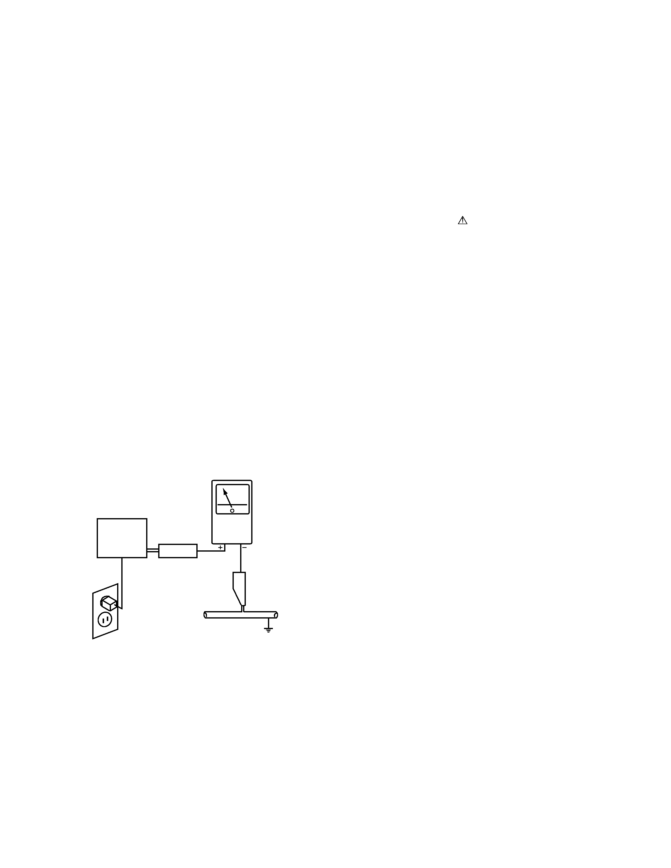
5. Before returning a serviced set to the customer, the
service technician must thoroughly test the unit to be
certain that it is completely safe to operate without
danger of electrical shock, and be sure that no protective
device built into the set by the manufacture has become
defective, or inadvertently defeated during servicing.
Therefore, the following checks should be performed
for the continued protection of the customer and service
technician.
6. Perform the following precautions against unwanted
radiation and rise in internal temperature.
· Always return the internal wiring to the original styling.
· Attach parts (Ground, Rear Cover, Shield Case) surely
after disassembly.
7. Perform the following precautions for the PDP panel.
· When the front case is removed, make sure nothing hits
the panel face, panel corner, and panel edge (so that
the glass does not break).
· Make sure that the panel vent does not break. (Check
that the cover is attached.)
· Handle the FPC connected to the panel carefully.
Twisting or pulling the FPC when connecting it to the
connector will cause it to peel off from the panel.
8. Pay attention to the following.
· Be sure to wire the fan. If the fan does not work, the
temperature will rise and cause the protection circuit
to operate.
· When the front case is removed, infrared ray is radiated
and may disturb reception of the remote control unit.
· Pay extreme caution when the front case and rear panel
are removed because this may cause a high risk of
disturbance to TVs and radios in the surrounding.
background image
PDP-501MX, PDP-V501X
3
Leakage Current Hot Check
Plug the AC line cord directly into an AC power source
(do not use an isolation transformer for this check).
Turn the AC power switch on.
Using a "Leakage Current Tester (Simpson Model 229
equivalent)", measure for current from all exposed metal
parts of the cabinet (input/output terminals, screwheads,
metal overlays, control shaft, etc.), particularly any
exposed metal part having a return path to the chassis, to a
known earth ground (water pipe, conduit, etc.). Any
current measured must not exceed 0.5mA.
Leakage
current
tester
Reading should
not be above
0.5mA
Device
under
test
Test all
exposed metal
surfaces
Also test with
plug reversed
(Using AC adapter
plug as required)
Earth
ground
AC Leakage Test
ANY MEASUREMENTS NOT WITHIN THE LIMITS
OUTLINED ABOVE ARE INDICATIVE OF A POTENTIAL
SHOCK HAZARD AND MUST BE CORRECTED BEFORE
RETURNING THE SET TO THE CUSTOMER.
1.2 PRODUCT SAFETY NOTICE
Many electrical and mechanical parts in PIONEER set have
special safety related characteristics. These are often not
evident from visual inspection nor the protection afforded
by them necessarily can be obtained by using replacement
components rated for higher voltage, wattage, etc.
Replacement parts which have these special safety
characteristics are identified in this Service Manual.
Electrical components having such features are identified
by marking with a
on the schematics and on the parts
list in this Service Manual.
The use of a substitute replacement component which dose
not have the same safety characteristics as the PIONEER
recommended replacement one, shown in the parts list in
this Service Manual, may create shock, fire or other
hazards.
Product Safety is continuously under review and new
instructions are issued from time to time. For the latest
information, always consult the current PIONEER Service
Manual. A subscription to, or additional copies of,
PIONEER Service Manual may be obtained at a nominal
charge from PIONEER.
Leakage Current Cold Check
With the AC plug removed from an AC power source, place
a jumper across the two plug prongs. Turn the AC power
switch on. Using an insulation tester (DC 500V), connect
one lead to the jumpered AC plug and touch the other lead
to each exposed metal part (input/output terminals,
screwheads, metal overlays, control shafts, etc.),
particularly any exposed metal part having a return path
to the chassis. Exposed metal parts having a return path to
the chassis should have a minimum resistor reading of
0.3M
and a maximum resistor reading of 5M. Any
resistor value below or above this range indicates an
abnormality which requires corrective action. Exposed
metal parts not having a return path to the chassis will
indicate an open circuit.
background image
PDP-501MX, PDP-V501X
4
7 Charged Section
The places where the commercial AC power is used
without passing through the power supply transformer.
If the places are touched, there is a risk of electric shock.
In addition, the measuring equipment can be damaged if it
is connected to the GND of the charged section and the
GND of the non-charged section while connecting the set
directly to the commercial AC power supply. Therefore,
be sure to connect the set via an insulated transformer and
supply the current.
7 Charged Section
(Power supply primary side)
1. AC Power Cord
2. AC Inlet with Filter
3. Power Switch (S1)
4. Fuse (In the MAIN POWER ASSY)
5. STB Transformer and Converter Transformer
(In the MAIN POWER ASSY)
6. Other primary side of the MAIN POWER ASSY
For the places, refer to the EXPLODED VIEWS, the
SCHEMATIC DIAGRAM and the PCB CONNECTION
DIAGRAM sections.
1.3 CHARGED SECTION AND HIGH VOLTAGE GENERATING POINT
7 High Voltage Generating Point
The places where voltage is 100V or more except for the
charged places described above. If the places are touched,
there is a risk of electric shock.
1. POWER SUPPLY MODULE (170V)
2. X DRIVE (A) ASSY
(170V)
3. X DRIVE (B) ASSY
(170V)
4. Y DRIVE (A) ASSY
(170V)
5. Y DRIVE (B) ASSY
(170V)
6. SCAN ASSY (A),(B),(C),(D) (150V)
For the places, refer to the EXPLODED VIEWS, the
SCHEMATIC DIAGRAM and the PCB CONNECTION
DIAGRAM sections.
POWER SUPPLY MODULE
Part is charged section.
Part is the high voltage generating points other than
the charged section.
Y DRIVE (A) ASSY
X DRIVE (A) ASSY
X DRIVE (B) ASSY
AC INLET
POWER SWITCH (S1)
Y DRIVE (B) ASSY
SCAN D ASSY
SCAN C ASSY
SCAN B ASSY
SCAN A ASSY
background image
PDP-501MX, PDP-V501X
5
2. EXPLODED VIEWS AND PARTS LIST
NOTES:
·Parts marked by "NSP" are generally unavailable because they are not in our Master Spare Parts List.
·The mark found on some component parts indicates the importance of the safety factor of the part. Therefore, when
replacing, be sure to use parts of identical designation.
·Screws adjacent to ¥mark on the product are used for disassembly.
2.1 PACKING
Mark
No.
Description
Part No.
Mark
No.
Description
Part No.
1
10
22
20
12
2
19
18
16
13
6
9
21
25
15
17
5
8
14
22
16
23
3
4
7
27
27
11
24
24
26
26
28
NSP
1
Battery (R6P,AA)
AEX-010
2
Rear Carton
AHB1201
3
Binder Assy
AEC1758
4
Wiping Cloth
AED1174
5
Under Pad R
AHA2213
6
Under Pad L
AHA2214
7
AC Power Cord
ADG1178
8
Mirror Mat
AHG1284
9
Remote Control (SR)
AXD1437
10
Under Pad C
AHA2215
11
Upper Pad R
AHA2216
12
Upper Pad L
AHA2217
13
Upper Carton (501MX)
AHD2980
13
Upper Carton (V501X)
AHD2979
14
Upper Pad C
AHA2218
15
Plasma Caution Sheet
ARM1145
16
Side Carton
AHB1196
17
Caution Sheet
ARM1146
18
Protect Sheet
SHC-925
19
Carton Cover
AHD2975
20
UNDER CARTON ASSY
AHD2976
21
Instruction Manual (501MX)
(English, French)
ARE1337
21
Instruction Manual (V501X)
(English, French)
ARE1339
22
Carton Spacer
AHB1198
23
Front Carton
AHB1200
24
BNC Conversion Connector
(501MX)
AKX1052
NSP
25
Warranty Card (501MX)
ARY1094
NSP
26
Label
VRW1629
NSP
27
Literature Bag
AHG-117
28
Battery Cover
AZN2379
PARTS LIST

Reviews

There are no reviews of this manual yet.