PIONEER PDP-427XG-DLFR[1] Service Manual

Cover page of PIONEER PDP-427XG-DLFR[1] Service Manual

Service Manual for PIONEER PDP-427XG-DLFR[1], downloadable as a PDF file.

Manual details

  • Immediate download after payment.
  • Delivered as a PDF file.
  • The manual has 103 pages
  • File size: 6.2 MB
  • Available language versions: English
  • Different language versions may vary sligthly in file size and page count.

We guarantee that...

  • our manuals are complete,
  • the manual includes circuit diagrams,
  • our manuals are checked with antivirus,
  • We'll issue refund if the manual is damaged, incomplete or unreadable (our refund policy)

Sample pages

Thumbnail of page 1Thumbnail of page 2Thumbnail of page 3Thumbnail of page 4
Thumbnail of page 5Thumbnail of page 6Thumbnail of page 7Thumbnail of page 8
Thumbnail of page 9
background image
ORDER NO.
PIONEER CORPORATION 4-1, Meguro 1-chome, Meguro-ku, Tokyo 153-8654, Japan
PIONEER ELECTRONICS (USA) INC. P.O. Box 1760, Long Beach, CA 90801-1760, U.S.A.
PIONEER EUROPE NV Haven 1087, Keetberglaan 1, 9120 Melsele, Belgium
PIONEER ELECTRONICS ASIACENTRE PTE. LTD. 253 Alexandra Road, #04-01, Singapore 159936
PIONEER CORPORATION 2006
ARP3424
T ­ ZZR OCT. 2006 Printed in Japan
PLASMA TELEVISION
PDP-427XG
PDP-427XDA
Model No.
Order No.
Remarks
PDP-427XD/WYVIXK5
ARP3391
EXPLODED VIEWS, BLOCK DIAGRAM, PCB PARTS LIST etc.
PDP-427XD/WYVIXK5
ARP3392
SCHEMATIC DIAGRAM, PCB CONNECTION DIAGRAM
¶ This service manual should be used together with the following manual(s):
THIS MANUAL IS APPLICABLE TO THE FOLLOWING MODEL(S) AND TYPE(S).
Model
Type
Power Requirement
Remarks
PDP-427XG
DLFR
AC 110 V to 240 V
PDP-427XDA
YP
AC 240 V
¶ For SPECIFICATIONS and PANEL FACILITIES, refer to the operating instructions.
background image
2
12
3
4
12
3
4
C
D
F
A
B
E
PDP-427XG
1. QUICK REFERENCE UPON SERVICE VISIT .......................................................................................................................... 3
2. CONTRAST OF MISCELLANEOUS PARTS ............................................................................................................................. 5
3. BLOCK DIAGRAM ................................................................................................................................................................... 14
3.1 SIGNAL BLOCK DIAGRAM ............................................................................................................................................ 14
4. DIAGNOSIS ............................................................................................................................................................................. 16
4.1 TROUBLE SHOOTING .................................................................................................................................................... 16
4.1.1 FLOWCHART OF FAILURE ANALYSIS FOR THE VIDEO SYSTEM .................................................................... 16
4.1.2 FLOWCHART OF FAILURE ANALYSIS FOR THE AUDIO SYSTEM ................................................................... 23
5. ADJUSTMENT ......................................................................................................................................................................... 28
5.1 ADJUSTMENT REQUIRED WHEN THE SET IS REPAIREO OR REPLACED ............................................................. 28
5.2 ADJUSTMENT REQUIRED WHEN PART IS REPLACED ............................................................................................. 29
5.3 ADJUSTMENT WHEN THE SERVICE PANEL ASSY IS REPLACED ............................................................................ 30
6. RS-232C .................................................................................................................................................................................. 32
6.1 OUT LINE OF RS-232C COMMAND .............................................................................................................................. 32
6.1.1 USING RS-232C COMMANDS ................................................................................................................................. 32
6.2 OUT LINE OF EACH COMMAND ................................................................................................................................... 33
6.2.1 QS6 ............................................................................................................................................................................ 33
7. GENERAL INFORMATION ...................................................................................................................................................... 34
7.1 LED INFORMATION ........................................................................................................................................................ 34
7.2 GENERAL INFORMATION (PDP-427XDA Only) ............................................................................................................ 35
7.3 SPECIFICATION .............................................................................................................................................................. 36
8. SERVICE FACTORY MODE .................................................................................................................................................... 37
8.1 FACTORY HIERARCHICAL TABLE ................................................................................................................................. 37
8.2 FACTORY MENU ............................................................................................................................................................. 39
8.2.1 INFORMATION .......................................................................................................................................................... 39
8.2.4 INITIALIZE ................................................................................................................................................................. 43
9. SCHEMATIC DIAGRAM .......................................................................................................................................................... 44
9.1 MAIN ASSY(1/9) [BOARD IF BLOCK] ........................................................................................................................... 44
9.2 MAIN ASSY(2/9) [REG 0 BLOCK] .................................................................................................................................. 46
9.3 MAIN ASSY(3/9) [ATUNER BLOCK] .............................................................................................................................. 48
9.4 MAIN ASSY(4/9) [AV SW BLOCK] ................................................................................................................................. 50
9.5 MAIN ASSY(5/9) [RGB SW BLOCK] .............................................................................................................................. 52
9.6 MAIN ASSY(6/9) [VDEC BLOCK] .................................................................................................................................. 54
9.7 MAIN ASSY(7/9) [IF UCOM BLOCK] ............................................................................................................................. 56
9.8 MAIN ASSY(8/9) [MAIN UCOM BLOCK] ....................................................................................................................... 58
9.9 MAIN ASSY(9/9) [DESEL BLOCK] ................................................................................................................................. 60
9.10 TANSHI ASSY (1/2) ...................................................................................................................................................... 62
9.11 TANSHI ASSY (2/2) ...................................................................................................................................................... 64
9.12 DTV MB ASSY (1/16) ................................................................................................................................................... 66
9.13 DTV MB ASSY (2/16) ................................................................................................................................................... 68
9.14 DTV MB ASSY (3/16) ................................................................................................................................................... 70
9.15 DTV MB ASSY (4/16) ................................................................................................................................................... 72
9.16 DTV MB ASSY (5/16) ................................................................................................................................................... 74
9.17 DTV MB ASSY (6/16) ................................................................................................................................................... 76
9.18 DTV MB ASSY (7/16) ................................................................................................................................................... 78
9.19 DTV MB ASSY (8/16) ................................................................................................................................................... 80
9.20 DTV MB ASSY (9/16) ................................................................................................................................................... 82
9.21 DTV MB ASSY (10/16) ................................................................................................................................................. 84
9.22 DTV MB ASSY (11/16) ................................................................................................................................................. 86
9.23 DTV MB ASSY (12/16) ................................................................................................................................................. 88
9.24 DTV MB ASSY (13/16) ................................................................................................................................................. 90
9.25 DTV MB ASSY (14/16) ................................................................................................................................................. 92
9.26 DTV MB ASSY (15/16) ................................................................................................................................................. 94
9.27 DTV MB ASSY (16/16) ................................................................................................................................................. 96
10. PCB CONNECTION DIAGRAM ............................................................................................................................................ 98
10.1 DTV MB ASSY ............................................................................................................................................................... 98
10.2 TANSHI, SIDE and PC ASSYS .................................................................................................................................... 102
CONTENTS
background image
3
1
234
12
3
4
C
D
F
A
B
E
PDP-427XG
1. QUICK REFERENCE UPON SERVICE VISIT
Notes when visiting for service
1. Notes when disassembling/reassembling
1 Rear case
When reassembling the rear case, the screws must be tightened in a
specific order. Be careful not to tighten them in the wrong order forcibly.
For details, see "Rear Case" in "6. DISASSEMBLY" on ARP3391.
2 Attaching screws for the HDMI connector
When attaching the HDMI connector after replacing the Main Assy,
secure the HDMI connector manually with a screwdriver, but not
with an electric screwdriver. If you tighten the screws too tightly
with an electric screwdriver, the screw heads may be damaged, in
which case the screws cannot be untightened/tightened any more.
2. On parts replacement
1 How to discharge before replacing the Assys
A charge of significant voltage remains in the Plasma Panel even
after the power is turned off. Safely discharge the panel before
replacement of parts, in either manner indicated below:
A: Let the panel sit at least for 3 minutes after the power is turned off.
B: Turn the Large Signal System off before the power is turned off
then, after 1 minute, turn the power off.
For details, see "10.3 Power ON/OFF Function for the Large-Signal
System" on ARP3391.
2 On the settings after replacement of the Assys
Some boards need settings made after replacement of the Assys.
For details, see "7. ADJUSTMENT" on ARP3391.
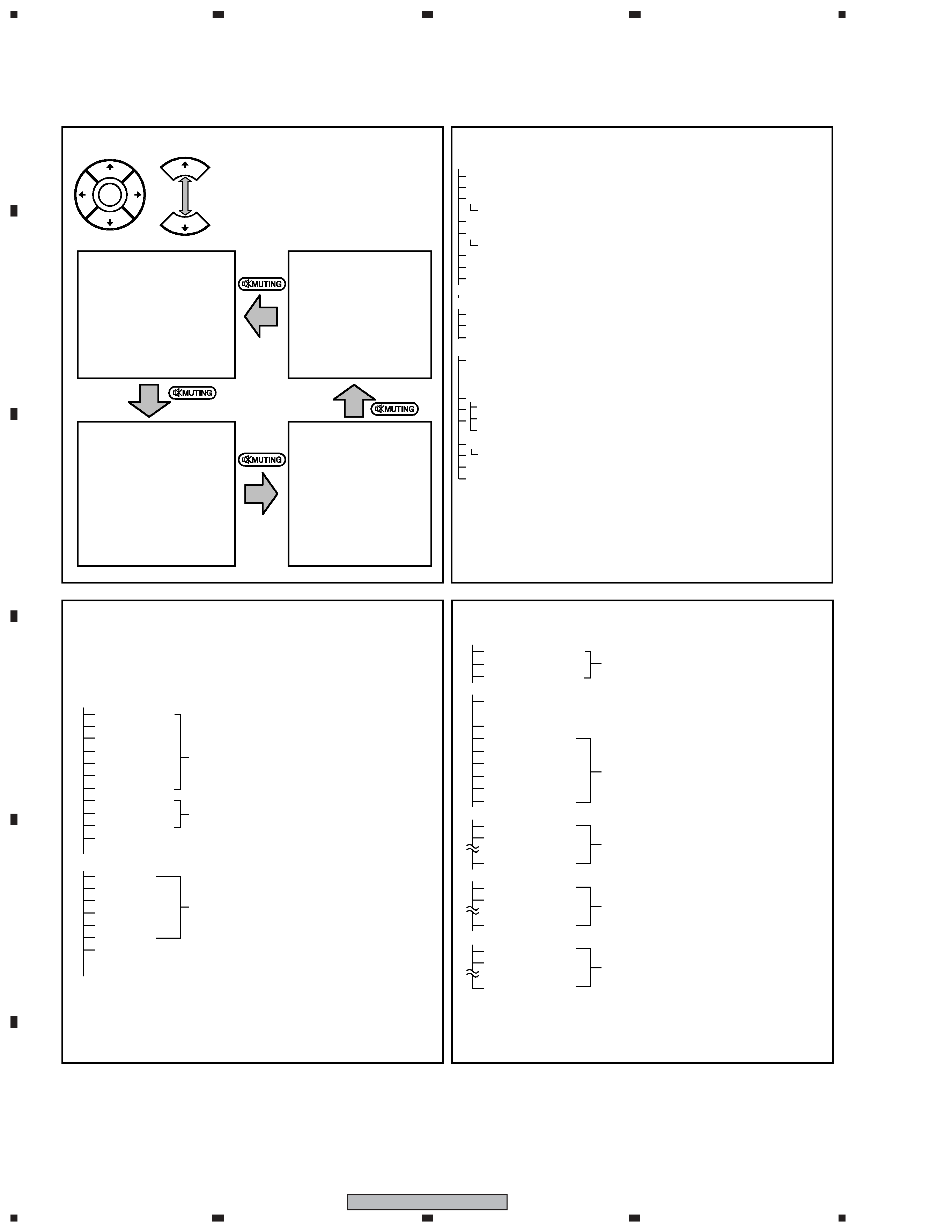
3. On various settings
1 SR+
After a repair using a PC, be sure to restore the setting for the
RS-232C connector to SR+.
2 Setting in Factory mode
After a Mask indication into the panel is performed, be sure to
set the Mask setting to "OFF" then exit Factory mode.
Adjustments and Settings after replacement of the
Assys (Procedures in Factory mode)
1. Digital Video Assy: Transfer of backup data
1 Select {PANEL FACTORY}, {ETC}, then {BACKUP DATA}. (After entering Factory
mode, press [MUTING] once, press [ENTER], press [
«] seven times, then press
[ENTER].)
2 Select {TRANSFER}, using [
\], then hold [ENTER] pressed for at least 5 seconds.
3 After transfer of backup data is completed, {ETC} is automatically selected, and the
LED on the front panel returns to normal lighting.
2. MAIN Assy : Switching to SR+ from RS-232C
1 Enter the Integrator mode. (The way is described above.)
2 As SR+ <=> is [OFF] state, switch to [ON] state by using [
\].
3 Turn the POWER switch of the main unit off by the remote control.
3. POWER SUPPLY Unit: Clearance of the accumulated power-on count
and maximum temperature value
1 Select {PANEL FACTORY}, {ETC}, then {P COUNT INFO}. (After entering Factory
mode, press [MUTING] once, press [ENTER], press [
«] seven times, press [ENTER],
then press [
«] six times.)
2 Press [
\] to select "CLEAR". Hold [ENTER] pressed for at least 5 seconds.
After clearance is completed, "ETC" is automatically selected. Clear the maximum
temperature value (MAX TEMP) in the same manner.
4. Other Assys: Clearance of the maximum temperature value
1 Select {PANEL FACTORY}, {ETC}, then {MAX TEMP}. (After entering Factory mode,
press [MUTING] once, press [ENTER], press [
«] seven times, press [ENTER], then
press [
«] seven times.)
2 Press [
\] to select "CLEAR". Hold [ENTER] pressed for at least 5 seconds.
After clearance is completed, "ETC" is automatically selected.
How to locate several items on the Factory menu
1. Confirmation of accumulated power-on time and power-on
count
Select {INFORMATION} then {HOUR METER}.
(After entering Factory mode, press [
«] four times.)
2. Confirmation of the Power-down and Shutdown histories
1 Panel system
PD: Select {PANEL FACTORY} then {POWER DOWN}.
(After entering Factory mode, press [MUTING] once, press
[ENTER], then press [
«] three times.)
SD: Select {PANEL FACTORY} then {SHUT DOWN}.
(After entering Factory mode, press [MUTING] once, press
[ENTER], then press [
«] four times.)
2 Main Assy
Select {INFORMATION} then {MAIN NG}.
(After entering Factory mode, press [
«] once.)
3. How to display the Mask indication
1 Mask indication in the panel side
1. Select {PANEL FACTORY} then {RASTER MASK SETUP}.
(After entering Factory mode, press [MUTING] once, press [ENTER],
then press [
«] 8 times.)
2. Press [ENTER], then select a Mask indication, using [
»] or [«].
2 Mask (SG screen) indication in the Main Assy (MAIN VDEC)
1. Select either Input 1, 2 or 4, to which no signal is input (black screen).
2. Select {INITIALIZE} then {SG MODE}. Press [
|]. (After entering
Factory mode, press [MUTING] three, then press [
«] once.)
Then, the indication at the lower right of the screen changes from
"OFF" to "ANA AD YCBCR".
3. You can change Mask patterns by pressing [
«] to select {SG
PATTERN} then using [
|] or [\].
Note: When you switch "SG MODE" routes, some displays become
monochrome, as they are in Y-signal only mode.
{
} : Item on the Factory menu
[
] : Key on the remote control unit
"
" : Screen indication
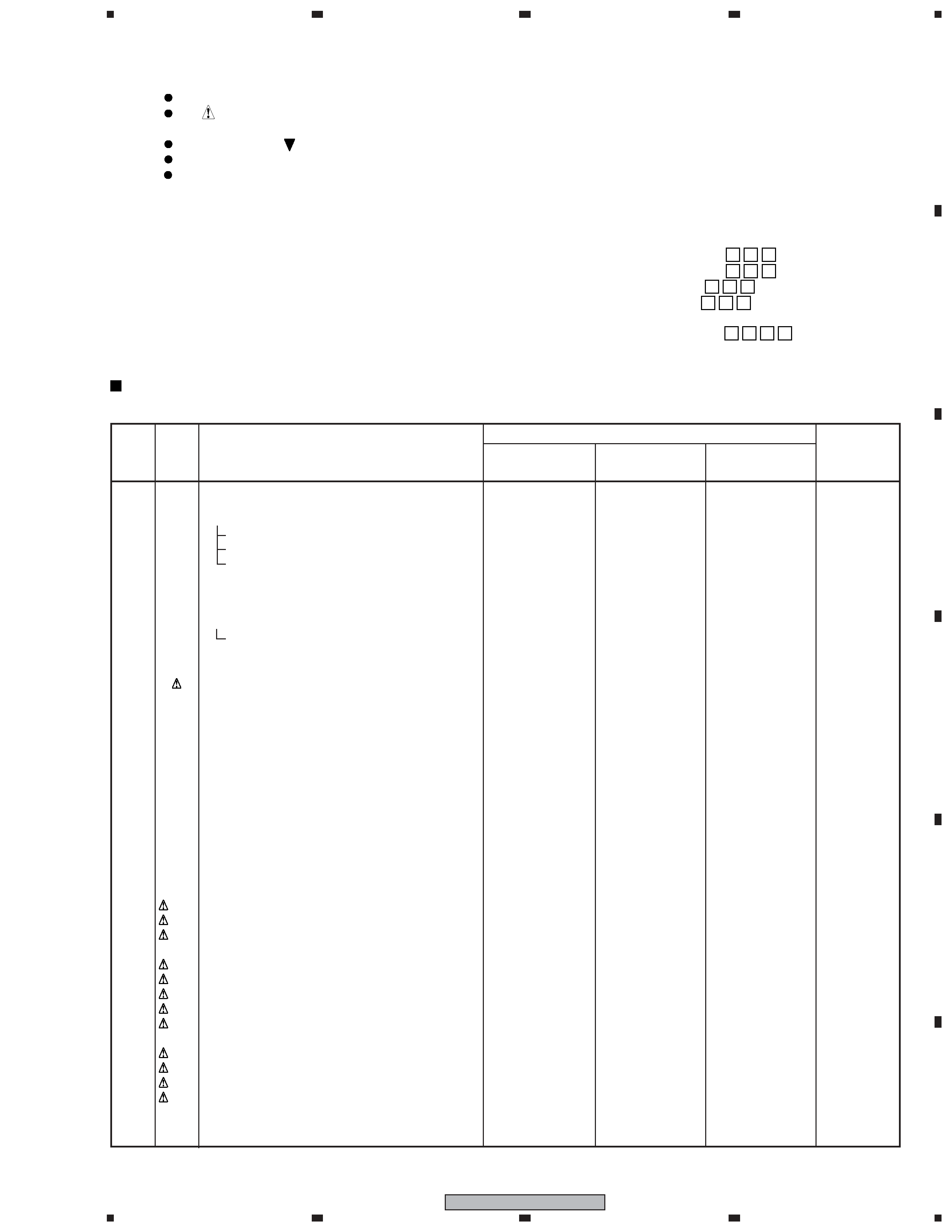
Item
No. of LEDs
flashing
PD/SD
Red 2
Red 3
Red 4
Red 5
Red 6
Red 7
Red 8
Red 9
Red 10
Red 11
Red 15
Blue 1
Blue 2
Blue 3
Blue 4
Blue 5
Blue 6
Blue 7
Blue 8
Blue 9
Blue 10
Blue 11
Blue 12
Blue 13
Red
Blue
Communication with the panel drive IC
Communication with the module IIC
DIGTAL-RST2
Panel high temperature
Audio
Communication with the Module microcomputer
Main 3-wire serial communication
Main IIC communication
Communication with the Main microcomputer
FAN
Unit high temperature
No corresponding item
MTB-RST2/RST4
PDP-427XDA, XG Quick Reference upon Service Visit
1
Notes, PD/SD diagnosis, and methods for various settings
POWER
SCAN
SCN-5V
Y-DRIVE
Y-DCDC
Y-SUS
ADRS
X-DRIVE
X-DCDC
X-SUS
UNKNOWN
P
anel
section
Main
section
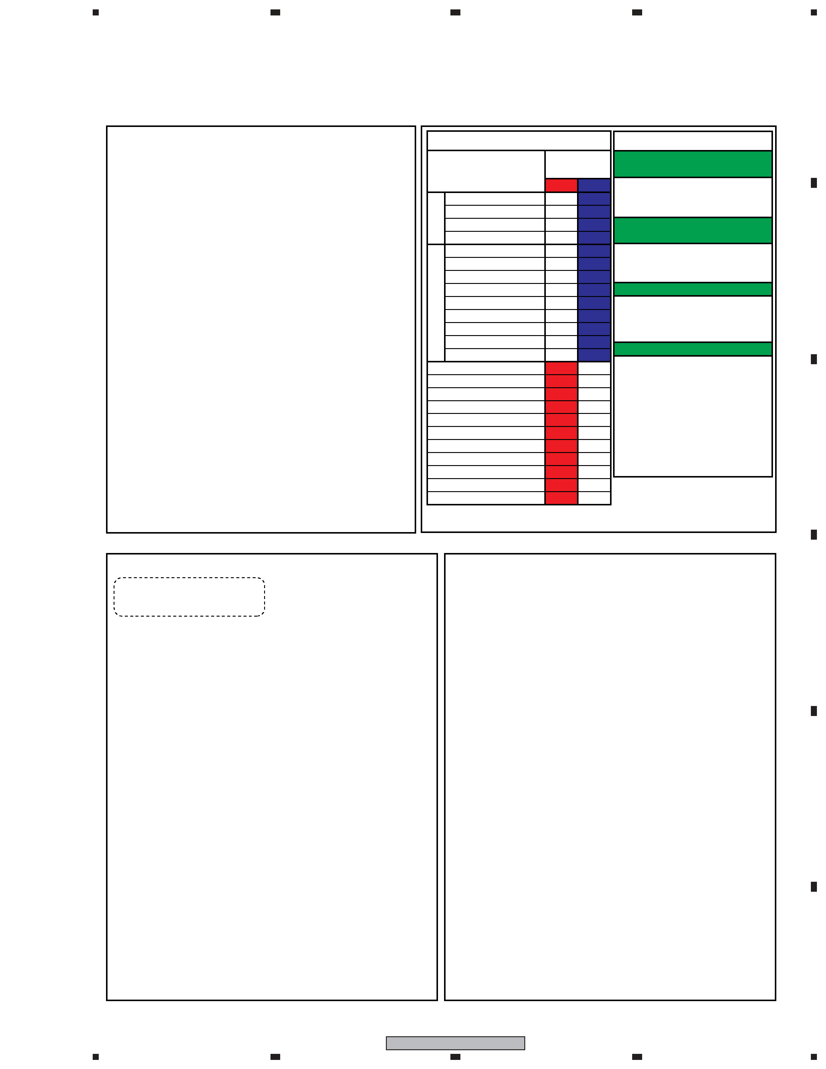
How to enter Integrator mode using
the supplied remote control unit
In the same way as with the remote
control unit supplied with the 6th-
generation model
1 Enter the Integrator mode.
2 Display "OFF" using [
\].
3 Change the communication speed
using [
«], then [\].
1 Enter the Standby mode.
2 Press [MENU].
3 Press [TV
].
1
Enter the Standby mode.
2
Hold [VOL +] or [VOL -] pressed for 3 seconds.
3
Hold [SPLIT] pressed for 3 seconds.
4-1 To set to 232C, press [ENTER].
5-2 To set to SR+, press [HOME MENU].
Note: If switching is completed successfully,
the red LED will flash twice.
Note 1: Use a remote control unit supplied with
the 6th-generation models or later.
Note 2: Do not hold a key pressed for more
than 5 seconds.
How to switch UART
2 (During Standby)
How to switch UART
1 (Integrator)
How to enter Factory mode using
the supplied remote control unit
Change of settings
background image
4
12
3
4
12
3
4
C
D
F
A
B
E
PDP-427XG
Structure of Layers in Service Factory Mode
INFORMATION mode
1. VERSION (1)
Flash Versions for PANEL system and MAIN system
2. VERSION (2)
Flash Versions for DTV system
3. MAIN NG
SD histories for MAIN (Going Clear model by SET key)
3-1. CLEAR
Select Yes by [
\] key \ pushing and hold [SET] key
4. TEMPERATURE
TEMP 1, TEMP2 and FAN mode are displayed
5. HOUR METER
Hour meter and number of Power ON are displayed
5-1. CLEAR
Select Yes by [
\] key \ pushing and hold [SET] key
6. HDMI SIGNAL INFO 1
For factory use
7. HDMI SIGNAL INFO 2
Signal info of HDMI are displayed ( Detail are on SM )
8. VDEC SIGNAL INFO
For factory use
PANEL FACTORY mode
Refer to [PANEL FACTORY MODE]
OPTION
1. EDID WRITE MODE
For factory use
2. CH PRESET
For production line use
3. AFT
For production line use
INITIALIZE
1. SYNC DET (+)
For factory use
2. SG MODE
SG signal from MAIN VDEC (Composite signal is required)
3. SG PATTERN
For factory use
4. SIDE MASK LEVEL(+)
For factory use
4-1. R MASK LEVEL
4-2. G MASK LEVEL
4-3. B MASK LEVEL
5. FINAL SETUP
Set to Factory default settings (it should perform after
5-1. DATA RESET
replacing a MAIN board )
6. CVT AUTO
For factory use
7. HDMI INTR POSITION(+)
For factory use
PDP-427XDA, XG Quick Reference upon Service Visit
2
Mode transition and structure of layers in Service Factory mode
Structure of Layers in Panel Factory Mode 1
1. PANEL INFORMATION
Version indication of the panel
2. PANEL WORKS
Indications of the accumulated power-on time, pulse-meter
count, and power-on count of the panel
3. POWER DOWN
Indication of the Power-down history
4. SHUT DOWN
Indication of the Shutdown history
5. PANEL-1 ADJ (+)
1. X-SUS B
2. Y-SUS B
3. Y-SUSTAIL T1
4. Y-SUSTAIL T2
Modification not required because these items are basically
5. Y-SUSTAIL W
for factory presetting
6. XY-RST W1
7. XY-RST W2
8. VOL SUS
9. VOL OFFSET
Settings required after replacement of the panel
10. VOL RST P
11. SUS FREQ.
For AM noise prevention (Depending on the mode,
brightness of the screen changes.)
6. PANEL-2 ADJ (+)
1. R-HIGH
2. G-HIGH
3 .B-HIGH
Parameters for the WB adjustment of the panel, which are
4. R-LOW
required during adjustment after panel replacement
5. G-LOW
6. B-LOW
7. ABL
Setting of the power consumption. A setting table is
available for each vertical signal.
To "Structure of Layers in Panel Factory Mode 2"
Structure of Layers in Panel Factory Mode 2
7. PANEL REVISE (+)
R-LEVEL
G-LEVEL
Items for use by engineers
B-LEVEL
8. ETC (+)
1. BACKUP DATA
For transferring backup data (after replacement of
the DIGITAL Assy)
2. DIGITAL EEPROM
To clear data of the digital video
3. PD INFO.
4. SD INFO.
For clearance of data for the corresponding items.
5. HR-MTR INFO.
The clearing method is the same: Select "CLEAR",
6. PM/B1-B5
using [
\], then hold [SET] pressed for at least 5
7. P COUNT INFO.
seconds. After clearance is completed, {ETC} is
8. MAX TEMP.
automatically selected.
9. RASTER MASK SETUP (+)
1. MASK OFF
2. RST MASK 01
For use while Raster Mask (full mask) is displayed.
· · · · ·
Use [
»] or [«] to select the type of mask.
25. RST MASK 24
10. PATTEN MASK SETUP (+)
1. MASK OFF
2. PTN MASK 01
For use while Pattern Mask is displayed. Use [
»] or
· · · · ·
[
«] to select the type of mask.
40. PTN MASK 39
11. COMBI MASK SETUP (+)
1. MASK OFF
2. CMB MASK 01
For use while Combination Mask is displayed.
· · · · ·
Use [
»] or [«] to select the type of mask.
11. CMB MASK 10
INFORMATION mode
1. VERSION (1)
2. VERSION (2)
3. MAIN NG
4. TEMPERATURE
5. HOUR METER
6. HDMI SIGNAL INFO1
7. HDMI SIGNAL INFO2
8. VDEC SIGNAL INFO
PANEL FACTORY mode
1. PANEL INFORMATION
2. PANEL WORKS
3. POWER DOWN
4. SHUT DOWN
5. PANEL-1 ADJ
6. PANEL-2 ADJ
7. PANEL REVICE
8. ETC.
9. RASTER MASK SETUP
10. PATTEN MASK SETUP
11. COMBI MASK SETUP
INITIALIZE mode
1. SYNC DET
2. SG MODE
3. SG PATTERN
4. SIDE MASK LEVEL
5. FINAL SETUP
6. CVT AUTO
7. HDMI INTR POSITION
OPTION mode
1. EDID WRITE MODE
2. CH PRESET
3. AFT
Up
Down
Enter
· To shift to another mode, press [MUTING].
· To shift to another item in a specific mode,
press [
»] or [«].
· To shift to the next nested layer below for an
item with a "(+)" indication, press [ENTER].
To return to the next nested layer above,
also press [ENTER].
Mode transition in Service Factory mode
background image
5
1
234
12
3
4
C
D
F
A
B
E
PDP-427XG
Part No.
Ref. No. Mark
Symbol and Description
PDP-427XA
PDP-427XG
PDP-427XDA
Remarks
/WYV5
/DLFR
/YP
PCB ASSEMBLIES
P23- 1
MAIN ASSY
AWV2318
AWV2322
AWV2322
NSP
IO ASSY
AWV2319
AWV2323
AWV2323
P23- 2
TANSHI ASSY
AWW1161
AWW1164
AWW1164
P13- 2
SIDE ASSY
AWW1162
AWW1165
AWW1165
P23- 3
PC ASSY
AWW1163
AWW1166
AWW1166
P19- 4
42 Y DRIVE ASSY
AWV2400
AWV2371
AWV2371
NSP
42 DIGITAL ASSY
AWV2435
AWV2372
AWV2372
P19- 5
42 DIGITAL ASSY
AWW1240
AWW1193
AWW1193
PACKING SECTION
P11- 1
Power Cord (2 m)
ADG1214
Not used
ADG1245
P11- 2
Power Cord LID
AHC1085
AHC1085
Not used
P11- 3
Remote Control Unit
AXD1540
AXD1543
AXD1542
P11- 4
Battery Cover
AZN2626
AZA7424
AZA7424
P11- 5
Operating Instructions (Italian, Dutch, Spanish)
ARC1563
Not used
Not used
P11- 6
Operating Instructions (English, French, German)
ARE1429
Not used
Not used
Operating Instructions (English, Spanish,
Not used
ARE1434
Not used
Portguese(B), Trad-Chinese)
Operating Instructions (English)
Not used
Not used
ARB1570
P11- 8
NSP
Dry Cell Battery (R06, AA)
VEM1031
AEX1025
VEM1031
P11-16 NSP
Polyethylene Bag
AHG1340
Not used
Not used
P11-15 NSP
Warranty Card
ARY1114
Not used
ARY1192
P11-24
Upper Carton
AHD3516
AHD3518
AHD3519
NSP
AC Power Cord
Not used
ADG1232
Not used
Accessories
NSP
AC Power Cord
Not used
ADG1233
Not used
Accessories
NSP
AC Power Cord
Not used
ADG1234
Not used
Accessories
NSP
AC Power Cord
Not used
ADG1235
Not used
Accessories
NSP
AC Power Cord
Not used
ADG1236
Not used
Accessories
NSP
AC Power Cord
Not used
ADG1238
Not used
Accessories
NSP
AC Power Cord
Not used
ADG1239
Not used
Accessories
NSP
AC Power Cord
Not used
ADG1241
Not used
Accessories
NSP
AC Power Cord
Not used
ADG1242
Not used
Accessories
NSP
AC Power Cord
Not used
ADG1243
Not used
Accessories
NSP
AC Power Cord
Not used
ADG1244
Not used
Accessories
NSP
AC Power Cord
Not used
ADG1246
Not used
Accessories
DTV Tuner Board
Not used
Not used
AXY1147
*
Filter
Not used
Not used
CTX1054
No. 1
2. CONTRAST OF MISCELLANEOUS PARTS
jp
f
y
For the applying amount of lubricants or glue, follow the instructions in this manual.
(In the case of no amount instructions, apply as you think it appropriate.)
Parts marked by "NSP" are generally unavailable because they are not in our Master Spare Parts List.
The
mark found on some component parts indicates the importance of the safety factor of the part.
Therefore, when replacing, be sure to use parts of identical designation.
Screws adjacent to
mark on product are used for disassembly.
Reference Nos. indicate the pages and Nos. in the service manual for the base model.
NOTES:
·When ordering resistors, first convert resistance values into code form as shown in the following examples.
Ex.1 When there are 2 effective digits (any digit apart from 0), such as 560 ohm and 47k ohm (tolerance is shown by J=5%,
and K=10%).
560
56
× 101
561 ........................................................ RD1/4PU 5 6 1 J
47k
47
× 103
473 ........................................................ RD1/4PU 4 7 3 J
0.5
R50 ..................................................................................... RN2H R 5 0 K
1
1R0 ..................................................................................... RS1P 1 R 0 K
Ex.2 When there are 3 effective digits (such as in high precision metal film resistors).
5.62k
562
× 101
5621 ...................................................... RN1/4PC 5 6 2 1 F
CONTRAST TABLE
PDP-427XG/DLFR, PDP-427XDA/YP and PDP-427XA/WYV5 are constructed the same except for the following :
* DTV Tuner Board has no Service part.

Reviews

There are no reviews of this manual yet.