PIONEER ELECTRONIC CORPORATION
4-1, Meguro 1-Chome, Meguro-ku, Tokyo 153-8654, Japan
PIONEER ELECTRONICS SERVICE INC.
P.O.Box 1760, Long Beach, CA 90801-1760 U.S.A.
PIONEER ELECTRONIC [EUROPE] N.V.
Haven 1087 Keetberglaan 1, 9120 Melsele, Belgium
PIONEER ELECTRONICS ASIACENTRE PTE.LTD. 253 Alexandra Road, #04-01, Singapore 159936
C PIONEER ELECTRONIC CORPORATION 1999
K-ZZA. FEB. 1999 Printed in Japan
CONTENTS
1. SAFETY INFORMATION ............................................1
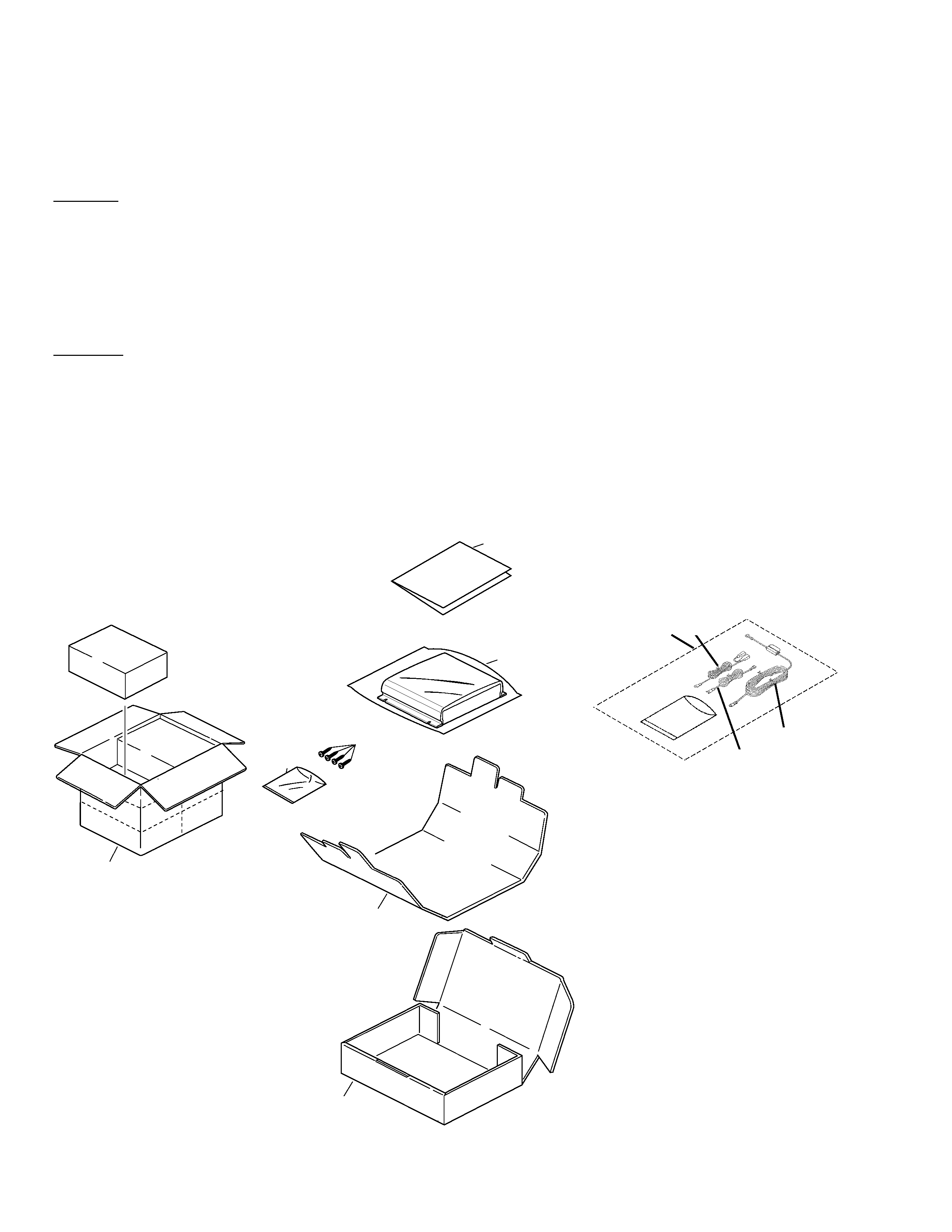
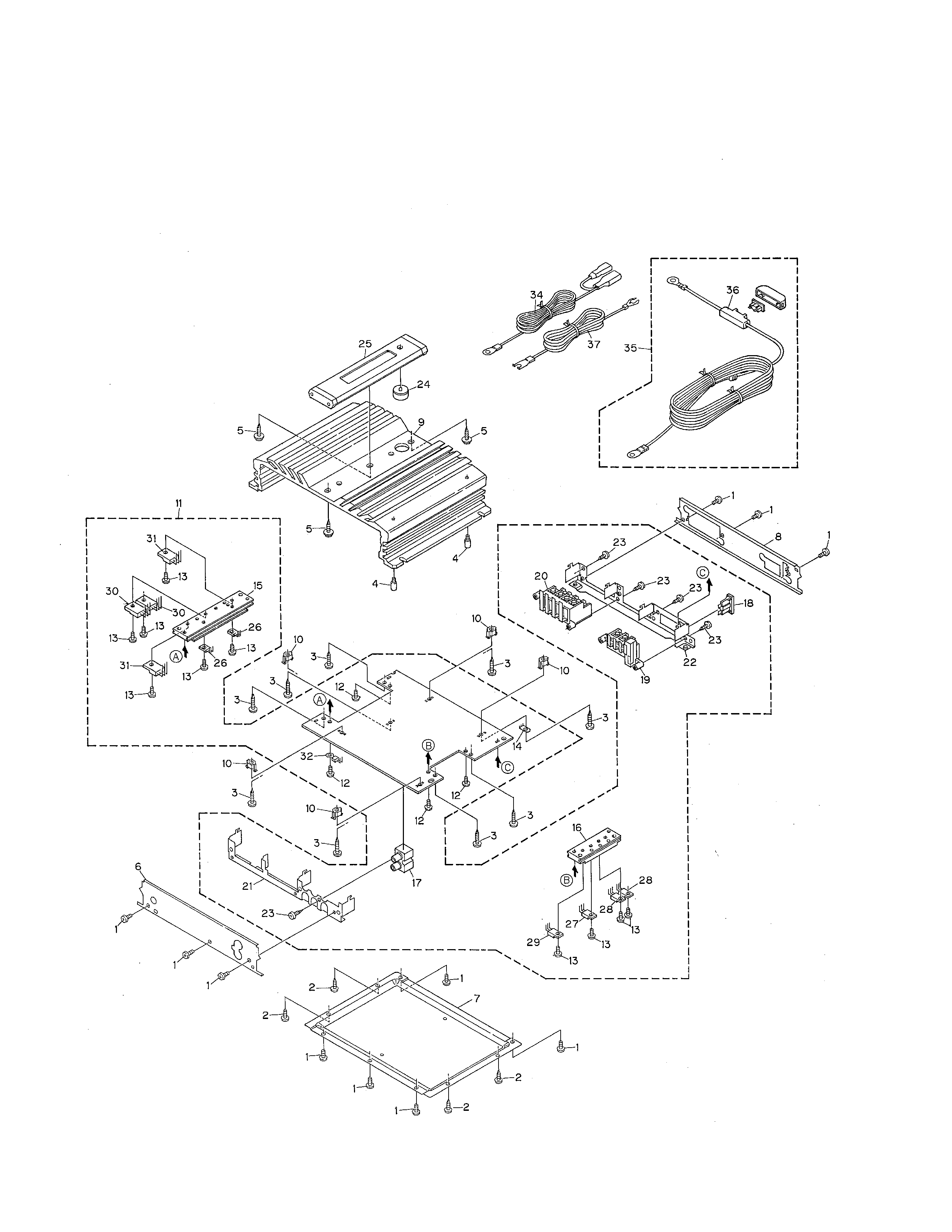
2. EXPLODED VIEWS AND PARTS LIST .......................2
3. SCHEMATIC DIAGRAM .............................................6
4. PCB CONNECTION DIAGRAM ..................................8
5. ELECTRICAL PARTS LIST ........................................10
6. ADJUSTMENT..........................................................13
7. GENERAL INFORMATION .......................................13
7.1 IC .........................................................................13
7.2 DISASSEMBLY ...................................................15
8. OPERATIONS AND SPECIFICATIONS.....................16
ORDER NO.
CRT2360
BRIDGEABLE POWER AMPLIFIER
GM-232
X1H/UC,EW,ES
GM-232/X1H/UC