PIONEER DVRRT602HS Service Manual

Cover page of PIONEER DVRRT602HS Service Manual

Service Manual for PIONEER DVRRT602HS, downloadable as a PDF file.

We also have owner's manual to this model.

Manual details

  • Immediate download after payment.
  • Delivered as a PDF file.
  • The manual has 174 pages
  • File size: 10.06 MB
  • Available language versions: English
  • Different language versions may vary sligthly in file size and page count.

We guarantee that...

  • our manuals are complete,
  • the manual includes circuit diagrams,
  • our manuals are checked with antivirus,
  • We'll issue refund if the manual is damaged, incomplete or unreadable (our refund policy)

Sample pages

Thumbnail of page 1Thumbnail of page 2Thumbnail of page 3Thumbnail of page 4
Thumbnail of page 5Thumbnail of page 6Thumbnail of page 7Thumbnail of page 8
Thumbnail of page 9
background image
ORDER NO.
PIONEER CORPORATION 4-1, Meguro 1-chome, Meguro-ku, Tokyo 153-8654, Japan
PIONEER ELECTRONICS (USA) INC. P.O. Box 1760, Long Beach, CA 90801-1760, U.S.A.
PIONEER EUROPE NV Haven 1087, Keetberglaan 1, 9120 Melsele, Belgium
PIONEER ELECTRONICS ASIACENTRE PTE. LTD. 253 Alexandra Road, #04-01, Singapore 159936
PIONEER CORPORATION 2006
STANDBY/ON
VHS EJECT
VIDEO L (MONO) · AUDIO · R
VHS
VHS/HDD/DVD
PAUSE LIVE TV
PLAY
COPY
SELECT
STOP REC
OPEN/CLOSE
AUTO
COPY
REC
VHS
DVD
START
CH
HDD
DVD
INPUT2
PAL SECAM
DVR-RT602H-S
RRV3429
DVD RECORDER
DVR-RT602H-S
THIS MANUAL IS APPLICABLE TO THE FOLLOWING MODEL(S) AND TYPE(S).
Model
Type
Power Requirement
Region No.
Remarks
DVR-RT602H-S
YXZT5
AC 220 V to 240 V
2
÷ When servicing this model, some service procedures may reset the customer settings
to the factory default settings. Make sure to explain this to the customer.
An HDD (Hard Disc Drive) is mounted in this product.
The HDD is a precision instrument very vulnerable to shock and electrostatic charges. Please read
"7.5 Cautions on Handling the HDD" in this manual and exercise sufficient caution when handling the
HDD itself, as well as the product with the HDD built in.
When an HDD becomes defective and inoperable, restoration of the user's data recorded on the HDD,
or copying of the user's recorded data to other media (such as a new HDD) is totally impossible.
Before servicing, OBTAIN THE USER'S PRIOR CONSENT to that effect.
The user must be made aware that all recorded data are deleted if the HDD is intialized.
For details, refer to "Important Check Points for Good Servicing" .
T-ZZV JUNE 2006 printed in Japan
background image
DVR-RT602H-S
2
12
34
12
3
4
C
D
F
A
B
E
SAFETY INFORMATION
LABEL CHECK
IMPORTANT
THIS PIONEER APPARATUS CONTAINS
LASER OF CLASS 1.
SERVICING OPERATION OF THE APPARATUS
SHOULD BE DONE BY A SPECIALLY
INSTRUCTED PERSON.
CLAMP signals for detecting the loading state are detected
by the drive CPUs, and the design prevents laser diode
oscillation when the CLAMP signal turns OFF.
In normal operation, if no disc is clamped, the laser diode
oscillation is disabled.
However, the interlock does not always operate in the test
mode.
2. When the cover is opened, close viewing of the objective
lens with the naked eye will cause exposure to a Class 3A
laser beam.
Additional Laser Caution
1. The ON/OFF(ON:low level,OFF:high level) status of the
LASER DIODE CHARACTERISTICS
MAXIMUM OUTPUT POWER: 100 mW
WAVELENGTH: 654 - 662 nm
LASER DIODE CHARACTERISTICS
MAXIMUM OUTPUT POWER: 5 mW
WAVELENGTH: 770 - 810 nm
7250000608
background image
DVR-RT602H-S
3
56
78
56
7
8
C
D
F
A
B
E
[Important Check Points for Good Servicing]
In this manual, procedures that must be performed during repairs are marked with the below symbol.
Please be sure to confirm and follow these procedures.
1. Product safety
Please conform to product regulations (such as safety and radiation regulations), and maintain a safe servicing environment by
following the safety instructions described in this manual.
1 Use specified parts for repair.
Use genuine parts. Be sure to use important parts for safety.
2 Do not perform modifications without proper instructions.
Please follow the specified safety methods when modification(addition/change of parts) is required due to interferences such as
radio/TV interference and foreign noise.
3 Make sure the soldering of repaired locations is properly performed.
When you solder while repairing, please be sure that there are no cold solder and other debris.
Soldering should be finished with the proper quantity. (Refer to the example)
4 Make sure the screws are tightly fastened.
Please be sure that all screws are fastened, and that there are no loose screws.
5 Make sure each connectors are correctly inserted.
Please be sure that all connectors are inserted, and that there are no imperfect insertion.
6 Make sure the wiring cables are set to their original state.
Please replace the wiring and cables to the original state after repairs.
In addition, be sure that there are no pinched wires, etc.
7 Make sure screws and soldering scraps do not remain inside the product.
Please check that neither solder debris nor screws remain inside the product.
8 There should be no semi-broken wires, scratches, melting, etc. on the coating of the power cord.
Damaged power cords may lead to fire accidents, so please be sure that there are no damages.
If you find a damaged power cord, please exchange it with a suitable one.
9 There should be no spark traces or similar marks on the power plug.
When spark traces or similar marks are found on the power supply plug, please check the connection and advise on secure
connections and suitable usage. Please exchange the power cord if necessary.
0 Safe environment should be secured during servicing.
When you perform repairs, please pay attention to static electricity, furniture, household articles, etc. in order to prevent injuries.
Please pay attention to your surroundings and repair safely.
2. Adjustments
To keep the original performance of the products, optimum adjustments and confirmation of characteristics within specification.
Adjustments should be performed in accordance with the procedures/instructions described in this manual.
4. Cleaning
For parts that require cleaning, such as optical pickups, tape deck heads, lenses and mirrors used in projection monitors, proper
cleaning should be performed to restore their performances.
3. Lubricants, Glues, and Replacement parts
Use grease and adhesives that are equal to the specified substance.
Make sure the proper amount is applied.
5. Shipping mode and Shipping screws
To protect products from damages or failures during transit, the shipping mode should be set or the shipping screws should be
installed before shipment. Please be sure to follow this method especially if it is specified in this manual.
background image
DVR-RT602H-S
4
12
34
12
3
4
C
D
F
A
B
E
CONTENTS
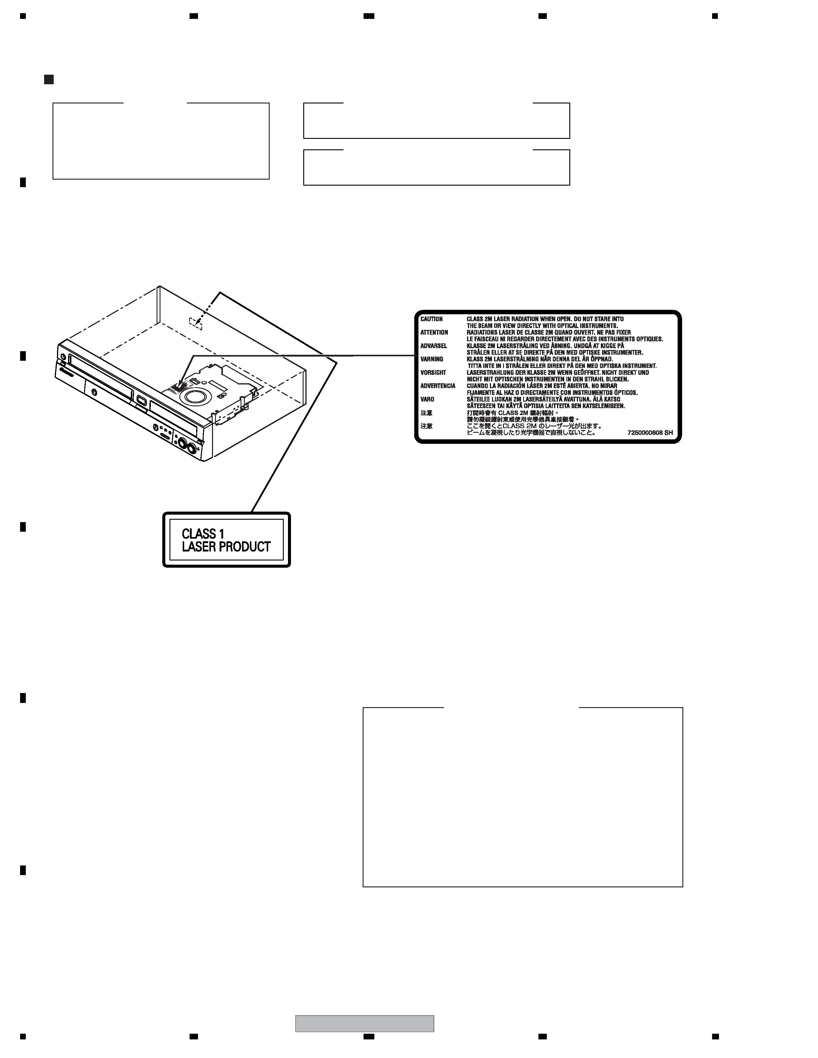
SAFETY INFORMATION ..................................................................................................................................... 2
1. SPECIFICATIONS ............................................................................................................................................ 6
2. EXPLODED VIEWS AND PARTS LIST .......................................................................................................... 10
2.1 PACKING ................................................................................................................................................. 10
2.2 EXTERIOR SECTION.............................................................................................................................. 12
2.3 FRONT PANEL SECTION ....................................................................................................................... 14
2.4 DECK ASSY (TOP SECTION) ................................................................................................................. 16
2.5 DECK ASSY (BOTTOM SECTION) ......................................................................................................... 18
2.6 WIRING CABLE ....................................................................................................................................... 20
3. BLOCK DIAGRAM AND SCHEMATIC DIAGRAM ..........................................................................................22
3.1 BLOCK DIAGRAM ................................................................................................................................... 22
3.1.1 OVERALL BLOCK DIAGRAM............................................................................................................ 22
3.1.2 Y/C/AUDIO/HEAD AMP BLOCK ........................................................................................................ 23
3.1.3 VCR MICON BLOCK ......................................................................................................................... 24
3.1.4 DISPLAY BLOCK ............................................................................................................................... 25
3.1.5 Hi-Fi BLOCK ...................................................................................................................................... 26
3.1.6 TUNER CONTROL BLOCK ............................................................................................................... 27
3.1.7 IN/OUT BLOCK.................................................................................................................................. 28
3.1.8 AV JACK/21PIN BLOCK .................................................................................................................... 29
3.1.9 REGULATOR BLOCK ........................................................................................................................ 30
3.1.10 POWER BLOCK .............................................................................................................................. 31
3.2 OVERALL WIRING DIAGRAM................................................................................................................. 32
3.3 SERVICE VCR ASSY (1/7) ...................................................................................................................... 34
3.4 SERVICE VCR ASSY (2/7) ...................................................................................................................... 36
3.5 SERVICE VCR ASSY(3/7) ....................................................................................................................... 38
3.6 SERVICE VCR ASSY(4/7) ....................................................................................................................... 40
3.7 SERVICE VCR ASSY(5/7) ....................................................................................................................... 42
3.8 SERVICE VCR ASSY(6/7) ....................................................................................................................... 44
3.9 SERVICE VCR ASSY(7/7) ....................................................................................................................... 46
3.10 AV PCB ASSY (1/3) ............................................................................................................................... 48
3.11 AV PCB ASSY (2/3) ............................................................................................................................... 50
3.12 AV PCB ASSY (3/3) ............................................................................................................................... 52
3.13 SERVICE MAIN ASSY(1/3) ................................................................................................................... 54
3.14 SERVICE MAIN ASSY(2/3) ................................................................................................................... 56
3.15 SERVICE MAIN ASSY(3/3) ................................................................................................................... 58
3.16 DISPLAY PCB, OPERATION 1 and 2 PCB ASSYS............................................................................... 60
3.17 RELAY 1 and 2 PCB ASSYS ................................................................................................................. 62
3.18 POWER PCB ASSY............................................................................................................................... 64
3.19 WAVE FORMS ....................................................................................................................................... 66
4. PCB CONNECTION DIAGRAM ..................................................................................................................... 71
4.1 SERVICE VCR ASSY .............................................................................................................................. 72
4.2 AV PCB, RELAY 1 and 2 PCB ASSYS .................................................................................................... 76
4.3 SERVICE MAIN ASSY ............................................................................................................................. 78
4.4 DISPLAY, OPERATION 1 and 2 PCB ASSYS.......................................................................................... 82
4.5 POWER PCB ASSY................................................................................................................................. 84
5. PCB PARTS LIST ........................................................................................................................................... 86
6. ADJUSTMENT ............................................................................................................................................... 91
6.1 PREVENTIVE CHECKS AND SERVICE INTERVALS............................................................................. 91
6.2 ADJUSTMENT ITEMS AND NECESSARY ADJUSTMENT POINTS...................................................... 93
6.3 SERVICING FIXTURES AND TOOLS ..................................................................................................... 94
6.4 SERVICE MODE LIST ............................................................................................................................. 95
6.5 MECHANICAL ADJUSTMENTS .............................................................................................................. 96
6.6 ELECTRICAL ADJUSTMENTS ............................................................................................................. 100
6.7 WHEN REPLACING EEPROM (MEMORY) IC ...................................................................................... 102
6.8 LD POWER ADJUSTMENT................................................................................................................... 103
7. GENERAL INFORMATION ........................................................................................................................... 105
7.1 DIAGNOSIS ........................................................................................................................................... 105
7.1.1 MODEL SETTING............................................................................................................................ 107
7.1.2 CPRM ID NUMBER AND DATA SETTING....................................................................................... 108
7.1.3 FIRMWARE DOWNLOADING METHOD......................................................................................... 112
7.1.4 VIDEO ADJUSTMENT FOR SPECIFIC AREA ................................................................................ 115
7.1.5 SERVICE MODE.............................................................................................................................. 119
7.1.6 EPG SERVICE MODE ..................................................................................................................... 131
7.1.7 AGING MODE.................................................................................................................................. 133
7.1.8 HDD CHECK MODE ........................................................................................................................ 135
background image
DVR-RT602H-S
5
56
78
56
7
8
C
D
F
A
B
E
7.1.9 DIAGNOSIS OF THE MAIN ASSY ...................................................................................................141
7.1.10 NOTE ON REPLACEMENT OF THE SDRAM................................................................................142
7.1.11 SETUP SEQUENCE.......................................................................................................................143
7.1.12 DISASSEMBLY...............................................................................................................................144
7.2 DISC REMOVAL METHOD ....................................................................................................................152
7.3 TAPE REMOVAL METHOD AT NO POWER SUPPLY ...........................................................................152
7.4 IC ............................................................................................................................................................153
7.5 CAUTIONS ON HANDLING THE HDD...................................................................................................163
7.6 KEY TO ABBREVIATIONS .....................................................................................................................165
7.7 DISC/CONTENT FORMAT .....................................................................................................................166
8. PANEL FACILITIES .......................................................................................................................................169

Reviews

There are no reviews of this manual yet.