PIONEER DVR-920H-S/WVXU Service Manual

Cover page of PIONEER DVR-920H-S/WVXU Service Manual

Service Manual for PIONEER DVR-920H-S/WVXU, downloadable as a PDF file.

We also have owner's manual to this model.

Manual details

  • Immediate download after payment.
  • Delivered as a PDF file.
  • The manual has 168 pages
  • File size: 13.24 MB
  • Available language versions: English
  • Different language versions may vary sligthly in file size and page count.

We guarantee that...

  • our manuals are complete,
  • the manual includes circuit diagrams,
  • our manuals are checked with antivirus,
  • We'll issue refund if the manual is damaged, incomplete or unreadable (our refund policy)

Sample pages

Thumbnail of page 1Thumbnail of page 2Thumbnail of page 3Thumbnail of page 4
Thumbnail of page 5Thumbnail of page 6Thumbnail of page 7Thumbnail of page 8
Thumbnail of page 9
background image
ORDER NO.
PIONEER CORPORATION 4-1, Meguro 1-chome, Meguro-ku, Tokyo 153-8654, Japan
PIONEER ELECTRONICS (USA) INC. P.O. Box 1760, Long Beach, CA 90801-1760, U.S.A.
PIONEER EUROPE NV Haven 1087, Keetberglaan 1, 9120 Melsele, Belgium
PIONEER ELECTRONICS ASIACENTRE PTE. LTD. 253 Alexandra Road, #04-01, Singapore 159936
PIONEER CORPORATION 2004
DVD RECORDER
DVR-920H
STOP REC
ONE TOUCH
COPY
PULL
OPEN
OPEN/CLOSE
HDD
HDMI
STB CONTROL
DVD
STANDBY / ON
REC
DVR-920H-S
RRV3051
DVD RECORDER
DVR-920H-S
THIS MANUAL IS APPLICABLE TO THE FOLLOWING MODEL(S) AND TYPE(S).
Model
Type
Power Requirement
Region No.
Serial No.
Please confirm 3rd & 4th
alphabetical letters.
DVR-920H-S
WYXU
AC220-240V
2
&&PG######$$
DVR-920H-S
WVXU
AC220-240V
2
&&PG######$$
÷ When servicing this model, some service procedures may reset the settings that customer set (*) to
the factory default settings. Make sure to explain this to the customer.
(*) : Initial Setup (Clock Setting, Remote Control Set, Channel settings, Video Out settings,
Audio In settings, Audio Out settings, Language settings)
Refer to the chapter 14 of the Operating Instructions for more details.
An HDD (Hard Disc Drive) is mounted in this product.
The HDD is a precision instrument very vulnerable to shock and electrostatic charges. Please read
"7.4 Cautions on Handling the HDD" in this manual and exercise sufficient caution when handling the
HDD itself, as well as the product with the HDD built in.
When an HDD becomes defective and inoperable, restoration of the user's data recorded on the HDD,
or copying of the user's recorded data to other media (such as a new HDD) is totally impossible.
Before servicing, OBTAIN THE USER'S PRIOR CONSENT to that effect.
The user must be made aware that all recorded data are deleted if the HDD is intialized.
For details, refer to "Important Check Points for Good Servicing" .
T-ZZV NOV. 2004 printed in Japan
background image
DVR-920H-S
2
12
34
12
3
4
C
D
F
A
B
E
SAFETY INFORMATION
LABEL CHECK
IMPORTANT
THIS PIONEER APPARATUS CONTAINS
LASER OF CLASS 1.
SERVICING OPERATION OF THE APPARATUS
SHOULD BE DONE BY A SPECIALLY
INSTRUCTED PERSON.
CLAMP signals for detecting the loading state are detected
by the drive CPUs, and the design prevents laser diode
oscillation when the CLAMP signal turns OFF.
In normal operation, if no disc is clamped, the laser diode
oscillation is disabled.
However, the interlock does not always operate in the test
mode.
2. When the cover is opened, close viewing of the objective
lens with the naked eye will cause exposure to a Class 3A
laser beam.
Additional Laser Caution
1. The ON/OFF(ON:low level,OFF:high level) status of the
LASER DIODE CHARACTERISTICS
MAXIMUM OUTPUT POWER: 70 mW
WAVELENGTH: 654 - 662 nm
LASER DIODE CHARACTERISTICS
MAXIMUM OUTPUT POWER: 100 mW
WAVELENGTH: 780 - 787 nm
DV
D
RE
CO
RD
ER
DV
R-9
20H
STO
P R
EC ON
E
TO
UC
H
CO
PY
PU
LL
OP
EN
OP
EN
/CL
OS
E
HD
D
HD
MI
ST
B
CO
NT
RO
L
DV
D
STA
ND
BY
/ O
N
RE
C
DRW2194
background image
DVR-920H-S
3
56
78
56
7
8
C
D
F
A
B
E
[Important Check Points for Good Servicing]
In this manual, procedures that must be performed during repairs are marked with the below symbol.
Please be sure to confirm and follow these procedures.
1. Product safety
Please conform to product regulations (such as safety and radiation regulations), and maintain a safe servicing environment by
following the safety instructions described in this manual.
1 Use specified parts for repair.
Use genuine parts. Be sure to use important parts for safety.
2 Do not perform modifications without proper instructions.
Please follow the specified safety methods when modification(addition/change of parts) is required due to interferences such as
radio/TV interference and foreign noise.
3 Make sure the soldering of repaired locations is properly performed.
When you solder while repairing, please be sure that there are no cold solder and other debris.
Soldering should be finished with the proper quantity. (Refer to the example)
4 Make sure the screws are tightly fastened.
Please be sure that all screws are fastened, and that there are no loose screws.
5 Make sure each connectors are correctly inserted.
Please be sure that all connectors are inserted, and that there are no imperfect insertion.
6 Make sure the wiring cables are set to their original state.
Please replace the wiring and cables to the original state after repairs.
In addition, be sure that there are no pinched wires, etc.
7 Make sure screws and soldering scraps do not remain inside the product.
Please check that neither solder debris nor screws remain inside the product.
8 There should be no semi-broken wires, scratches, melting, etc. on the coating of the power cord.
Damaged power cords may lead to fire accidents, so please be sure that there are no damages.
If you find a damaged power cord, please exchange it with a suitable one.
9 There should be no spark traces or similar marks on the power plug.
When spark traces or similar marks are found on the power supply plug, please check the connection and advise on secure
connections and suitable usage. Please exchange the power cord if necessary.
0 Safe environment should be secured during servicing.
When you perform repairs, please pay attention to static electricity, furniture, household articles, etc. in order to prevent injuries.
Please pay attention to your surroundings and repair safely.
2. Adjustments
To keep the original performance of the products, optimum adjustments and confirmation of characteristics within specification.
Adjustments should be performed in accordance with the procedures/instructions described in this manual.
4. Cleaning
For parts that require cleaning, such as optical pickups, tape deck heads, lenses and mirrors used in projection monitors, proper
cleaning should be performed to restore their performances.
3. Lubricants, Glues, and Replacement parts
Use grease and adhesives that are equal to the specified substance.
Make sure the proper amount is applied.
5. Shipping mode and Shipping screws
To protect products from damages or failures during transit, the shipping mode should be set or the shipping screws should be
installed before shipment. Please be sure to follow this method especially if it is specified in this manual.
background image
DVR-920H-S
4
12
34
12
3
4
C
D
F
A
B
E
CONTENTS
SAFETY INFORMATION ..................................................................................................................................... 2
1. SPECIFICATIONS ............................................................................................................................................ 5
2. EXPLODED VIEWS AND PARTS LIST ............................................................................................................ 8
2.1 PACKING ................................................................................................................................................... 8
2.2 EXTERIOR (TOP) SECTION ................................................................................................................... 10
2.3 EXTERIOR (BOTTOM) SECTION ........................................................................................................... 12
2.4 FRONT PANEL SECTION ....................................................................................................................... 14
3. BLOCK DIAGRAM AND SCHEMATIC DIAGRAM ..........................................................................................16
3.1 BLOCK DIAGRAM ................................................................................................................................... 16
3.1.1 OVERALL BLOCK DIAGRAM............................................................................................................ 16
3.1.2 POWER BLOCK DIAGRAM............................................................................................................... 19
3.2 OVERALL WIRING DIAGRAM................................................................................................................. 22
3.3 TUJB ASSY(1/3) ...................................................................................................................................... 24
3.4 TUJB ASSY(2/3) ...................................................................................................................................... 26
3.5 TUJB ASSY(3/3) ...................................................................................................................................... 28
3.6 ATAB ASSY .............................................................................................................................................. 29
3.7 SCRB ASSY ............................................................................................................................................ 30
3.8 MAIN ASSY(1/5) ...................................................................................................................................... 32
3.9 MAIN ASSY(2/5) ...................................................................................................................................... 34
3.10 MAIN ASSY(3/5) .................................................................................................................................... 36
3.11 MAIN ASSY(4/5) .................................................................................................................................... 38
3.12 MAIN ASSY(5/5) .................................................................................................................................... 40
3.13 FLKY, FRJB and PSWB ASSYS ............................................................................................................ 42
3.14 POWER SUPPLY UNIT.......................................................................................................................... 44
3.15 WAVE FORMS ....................................................................................................................................... 46
4. PCB CONNECTION DIAGRAM ..................................................................................................................... 50
4.1 ATAB ASSY .............................................................................................................................................. 51
4.2 TUJB ASSY.............................................................................................................................................. 52
4.3 SCRB ASSY ............................................................................................................................................ 56
4.4 MAIN ASSY ............................................................................................................................................. 58
4.5 FLKY, FRJB and PSWB ASSYS .............................................................................................................. 62
4.6 POWER SUPPLY UNIT............................................................................................................................ 66
5. PCB PARTS LIST ........................................................................................................................................... 68
6. ADJUSTMENT ............................................................................................................................................... 74
6.1 TUJB ASSY ADJUSTMENT .................................................................................................................... 74
6.2 MAIN ASSY ADJUSTMENT .................................................................................................................... 75
7. GENERAL INFORMATION ............................................................................................................................. 76
7.1 DIAGNOSIS ............................................................................................................................................. 76
7.1.1 MODEL SETTING.............................................................................................................................. 77
7.1.2 FIRMWARE DOWNLOADING METHOD........................................................................................... 78
7.1.3 CPRM ID NUMBER AND DATA SETTING......................................................................................... 81
7.1.4 VIDEO ADJUSTMENT FOR SPECIFIC AREA .................................................................................. 85
7.1.5 LOW-LEVEL LIMITTER SWITCHING SETTING ............................................................................... 89
7.1.6 RGB INPUT LEVEL SETTING........................................................................................................... 90
7.1.7 SERVICE MODE................................................................................................................................ 92
7.1.8 ERROR RATE MEASUREMENT ..................................................................................................... 106
7.1.9 DV SERVICE MODE ........................................................................................................................ 108
7.1.10 EPG SERVICE MODE ................................................................................................................... 111
7.1.11 AGING MODE................................................................................................................................ 113
7.1.12 SERVICE MODE FOR SDRAM FOR NEW DEVICE..................................................................... 115
7.1.13 SERVICE MODE FOR HDMI ......................................................................................................... 116
7.1.14 TROUBLESHOOTING FOR HDMI................................................................................................. 119
7.1.15 SETUP SEQUENCE ...................................................................................................................... 122
7.1.16 DISASSEMBLY .............................................................................................................................. 123
7.2 IC ........................................................................................................................................................... 128
7.3 OUTLINE OF THE PRODUCT............................................................................................................... 156
7.4 CAUTIONS ON HANDLING THE HDD .................................................................................................. 159
7.5 DISC/CONTENT FORMAT .................................................................................................................... 161
7.6 CLEANING............................................................................................................................................. 162
8. PANEL FACILITIES ...................................................................................................................................... 163
background image
DVR-920H-S
5
56
78
56
7
8
C
D
F
A
B
E
1. SPECIFICATIONS
Specifications
General
System
HDD, DVD-Video, DVD-R/RW,
Video-CD, Super VCD, CD,
CD-R/RW (WMA, MP3, JPEG, CD-DA)
Power requirements
220­240 V, 50/60 Hz
Power consumption
62 W
Power consumption in standby mode
0.7 W
(Front panel display: off)
Weight
7.9 kg
Dimensions
420 (W) x 87 (H) x 357 (D) mm
Operating temperature
+5°C to +35°C
Operating humidity
5% to 85%
(no condensation)
TV system
PAL/SECAM/NTSC (external input only)
Recording
Recording format
DVD Video Recording, DVD-VIDEO
Recordable discs
DVD-RW (DVD Re-recordable disc)
DVD-R (DVD Recordable disc)
Video recording format
Sampling frequency
13.5MHz
Compression format
MPEG
Audio recording format
Sampling frequency
48kHz
Compression format
DolbyDigital or Linear PCM
(uncompressed)
Recording time
HDD
Fine (FINE)
Approx. 54 hours
Standard Play (SP)
Approx. 108 hours
Long Play (LP)
Approx. 216 hours
Extended Play (EP)
Approx. 324 hours
Super Long Play (SLP)
Approx. 433 hours
Manual Mode (MN)
Approx. 54­433 hours
DVD-R/DVD-RW
Fine (FINE)
Approx. 1 hour
Standard Play (SP)
Approx. 2 hours
Long Play (LP)
Approx. 4 hours
Extended Play (EP)
Approx. 6 hours
Super-Long Play (SLP)
Approx. 8 hours
Manual Mode (MN)
Approx. 1­8 hours
Tuner
Receivable channels
. . . . . . . . . . . . . . . . . . . . . . .
. . . . . . . . . . . . . . . . . . . .
. . . . . . . . . . . . . . . . . . .
. . . . . . . . . . . . . . . . . . .
. . . . . . . . . . . . .
. . . . . . . . . . .
. . . . . . . . . . . . . . . . . . . . . . . . . . . . . . . . .
. . . . . . . . . . . .
. . . . . . . . . . . . . . . . . . . . . . . . . . . . . . . . . .
. . . . . . . . . . . . . . . . . . . . . . . . . . . . . . . . . . .
. . . . . . . . . . . . . . . . . . . . . . . . . . . . . . .
. . . . . . . . . . . . . . . . . . . . . .
. . . . . . . . . . . . . . . . . . . . . .
. . . . . . . . . . . .
. . . . . . . . . . . . . . . . . . . . . . . . . . . . . . .
. . . . . . . . . . . . . . . . . . . . . . . . . . . . . . . . . . . . . . . .
. . . . . . . . . . . . . . . . . . . . . . . . . . . . . . . . . .
. . . . . . . . . . . . . . . . . . . . . . . . . . . . .
. . . . . . . . . . . . . . . . . . . . . . . . . . . . . . . . .
. . . . . . . . . . . . . . . . . . . . . . . . . . . . . . .
. . . . . . . . . . . . . . . . . . . . .
. . . . . . . . . . .
. . . . . . . . . . . . . . . . . . . . . . . . . . . . . . . . .
. . . . . . . . . . . . . . . . . . . . . . . . . . . . . . . . . .
. . . . . . . . . . . . . . . . . . . . . . . . . . . . . . . .
. . . . . . . . . . . . . . . . . . . . . . . . . . . . . . . . . . . . . .
. . . . . . . . . . . . . . . . . . . . . . . . . . . . . . . . . . . .
. . . . . . . . . . . . . . . . . . . . . . . . . . . .
. . . . . . . . . . . . . . . . . . . . . . . . . . . . . . . . . . . . . .
. . . . . . . . . . . . . . . . . . . . . . . . . . . . . . . . . . . . . . . . . .
. . . . . . . . . . . . . . . . . . . . . . . . . . . .
. . . . . . . . . . . . . . . . . . . . . . . . . . . . . . . . . . . . . .
. . . . . . . . . . . . . . . . . . . . . . . . . . . . . . . . . .
. . . . . . . . . . . . . . . . . . . . . . . . . . . . . . . . . . . . . . . . . . . . . . .
. . . . . . . . . . . . . . . . . . . . . . . . . . . . . . . . . . . . . . . . . . . . . . .
. . . . . . . . . . . . . . . . . . . . . . . . . . . . . . . . . . . . . . . . . .
. . . . . . . . . . . . . . . . . . . . . . . . . . . .
. . . . . . . . . . . . . . . . . . . . . . . . . . . . . . . . . . . .
. . . . . . . . . . . . . . . . . . . . . . . . . . . . . . . . . . . . . . . . . . . . . .
. . . . . . . . . . . . . . . . . . . . . . . . . . . . . . . . . . . . . . . . . . . . . . .
. . . . . . . . . . . . . . . . . . . . . . . . . . . . . . . . . . . . . . . .
. . . . . . . . . . . . . . . . . . . . . . . . . . . . . . . . . . . . . . . . .
. . . . . . . . . . . . . . . . . . . . . . . . . . . . . . . . . . . . . . . . . .
. . . . . . . . . . . . . . . . . . . . . . . . . . . . . . . . . . . . . . . . .
. . . . . . . . . . . . . . . . . . . . . . . . . . . . . . . . . . . . . .
. . . . . . . . . . . . . . . . . . . . . . . . . . . . . . . .
. . . . . . . . . . . . . . . . . . . . . .
. . . . . . . . . . . . . . . . . . . . . . . . . . . . . . . . . . . . . . . .
. . . . . . . . . . . . . . . . . . .
. . . . . . . . . . . . . . . . . . . . . . . . .
. . . . . . . . . . . . . .
. . . . . . . . . . . . . . .
. . . . . . . . . . . . . . . . . . . . . . . . . . . . . . .
. . . . . . . . . . . . . . . . . . . . . . .
. . . . . . . . . . . . . . . . . . . . . . . .
. . . . . . . . . . . . . . . . . . . . . . .
. . . . . . . .
. . . . . . . . . . . . . . . . . . . . . . . . . . . . . . . . . . . . . . . . . . .
. . . . . . . . . . . . . . . . . . . . . . . . . . . . . .
. . . . . . . . . . . . . . . . . . . . . . . . . . . . . . .
. . . . . . . . . . . . . . . . . . . . . . . . . . . . . . . .
. . . . . . . . . . . . . . . . . . . . . . . . . . . . . . . . .
. . . . . . . . . . . . . . . . . . . . . . . . . . . . . . .
. . . . . . . . . . . . . . . . . . . . . . . . . . . . . . . . .
. . . . . . . . . . . . . . . . . . . . . . . . .
. . . . . . . . . . . . . . . . . . . . . . . . . . . . .
. . . . . . . . . . . . . . . . . . . . . . . .
. . . . . . . . . . . . . . . . . . . . . . . . . . . . . . . . . . . .
. . . . . . . . . . . . . . . . . . . .
. . . . . . . . . .
. . . . . . . . . . .
. . . . . . . . . . . . . . . . . . . . . . . . .
. . . . . . . . . . . . . . . . . . . . . .
. . . . . . . . . . . . . . . . . . . . . . .
. . . . . . . . . . . . . . . . . . . . . . . . . . .
. . . . . . . . . . . . . . . . . . . . . . .
. . . . . . . . . . . . . . . . . . . . .
. . . . . . . . . . . . . . . . . . . . .
. . . . . . . . . . . . . . . . . . . . . . . .
. . . . . . . . . . . . . . .
. . . . . . . . . . . . . . . . . . . . . . .
Jacks
AV connector 2 (Input 1),RCA jack (Input 2, 3)
Video output
AV1 Output
Output level
1 Vp-p (75
)
Jacks
AV connector 1 (AV1)
RCA jack (Output)
S-Video input
Input 1, 3 (rear), 2 (front)
Y (luminance) - Input level
1 Vp-p (75
)
C (colour) - Input level
300 mVp-p (75
)
Jacks
AV connector 2 (Input 1), 4 pin mini DIN (Input 2, 3)
S-Video output
AV1 / Output
Y (luminance) - Output level
1 Vp-p (75
)
C (colour) - Output level
300 mVp-p (75
)
Jacks
AV connector 1 (AV1),4 pin mini DIN (Output)
Component video output
Output level
Y: 1.0 Vp-p (75
)
PB, PR : 0.7 Vp-p (75
)
Jacks
RCA jacks
RGB input
Input level
0.7 Vp-p (75
)
Jacks
AV connector 2 (Input 1)
RGB output
Output level
0.7 Vp-p (75
)
Jacks
AV connector 1 (AV1)
Audio input
Input 1, 3 (rear), 2 (front) L/R
Input level
During audio input
2V rms
(Input impedance: more than 22 k
)
Jacks
AV connector 2 (Input 1), RCA jacks (Input 2, 3)
Audio output
AV1 Output
During audio output
2V rms
(Output impedance: less than 1.5 k
)
Jacks
AV connector 1 (AV1),RCA jacks (Output)
Digital audio output
optical / coaxial
DV input/output
4pin (i.LINK/IEEE 1394 standard)
HDMI output
19 pin
Control input
Mini jack
G-LINK
Mini jack
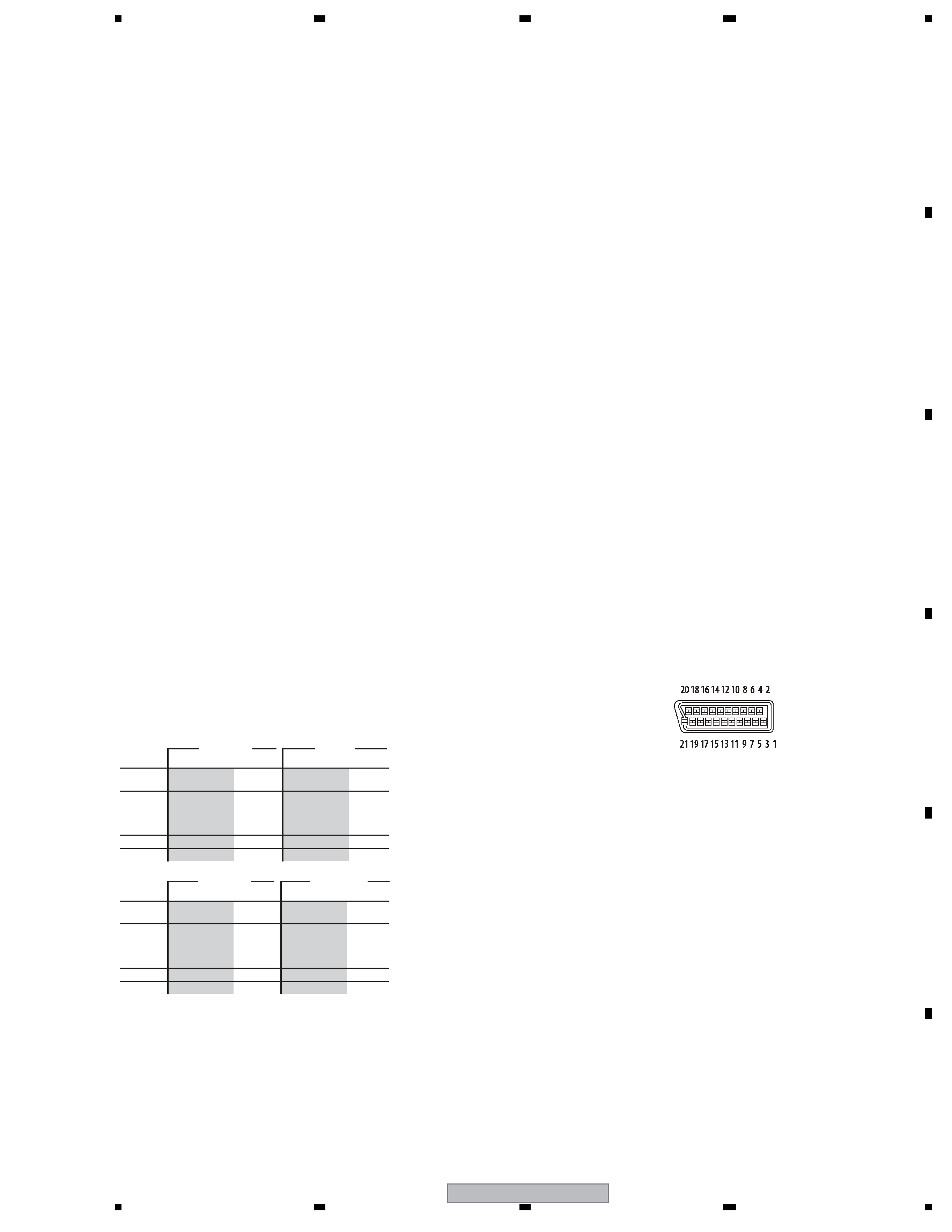
AV Connectors (21-pin connector assignment)
AV connector input/output
21-pin connector
This connector provides the video and audio signals for
connection to a compatible colour TV or monitor.
PIN no.
AV1(RGB)-TV / AV2(INPUT 1)
1
Audio 2/R out / Audio 2/R out
2
­ / Audio 2/R in
11
G out / G in
3
Audio 1/L out / Audio 1/L out
6
­ / Audio 1/L in
15
R or C out / R or C in
4
GND
17
GND
7
B out / B in
19
Video out or Y out / Video out
20
­ / Video in or Y in
8
Status
21
GND
Supplied accessories
Remote control
1
AA/R6P dry cell batteries
2
Audio / Video cable (red/white/yellow)
1
RF antenna cable
1
G-LINK cable
1
Power cable
1
Operating Instructions
Warranty card
1
Note: The specifications and design of this product are subject
to change without notice, due to improvement.
STEREO
B/G - A2
I - NICAM
L - NICAM
B/G - NICAM
D/K - NICAM
VHF (low)
VHF (high)
Hyper
UHF
VHF (low)
VHF (high)
Hyper
UHF
Channel
E2 - E4
X - Z
E5 - E12
S1 - S20
M1 - M10
U1 - U10
S21 - S41
E21 - E69
Frequency
47 - 89 MHz
104 - 300 MHz
302 - 470 MHz
470 - 862 MHz
Channel
A - C
X - Z
D - J
11, 13
S1 - S20
S21 - S41
E21 - E69
Frequency
44 - 89 MHz
104 - 300 MHz
302 - 470 MHz
470 - 862 MHz
PAL B/G
PAL I
Channel
2 - 4
5 - 10
B - Q
S21 - S41
21 - 69
Frequency
49 - 65 MHz
104 - 300 MHz
300 - 470 MHz
470 - 862 MHz
Channel
R1 - R5
R6 - R12
S1 - S20
S21 - S41
E21 - E69
Frequency
49 - 94 MHz
104 - 300 MHz
302 - 470 MHz
470 - 862 MHz
SECAM L
SECAM D/K
Timer
Programs
1 month/32 programs
Clock
Quartz lock (24-hour digital display)
Power off memory
Approx. 5 years (after manufacture)
Input/Output
VHF/UHF antenna input/output terminal
VHF/UHF set
75
(IEC connector)
Video input
Input 1, 3 (rear), 2 (front)
Input level
1 Vp-p (75
)

Reviews

There are no reviews of this manual yet.