DVR-320-S
4
12
34
12
3
4
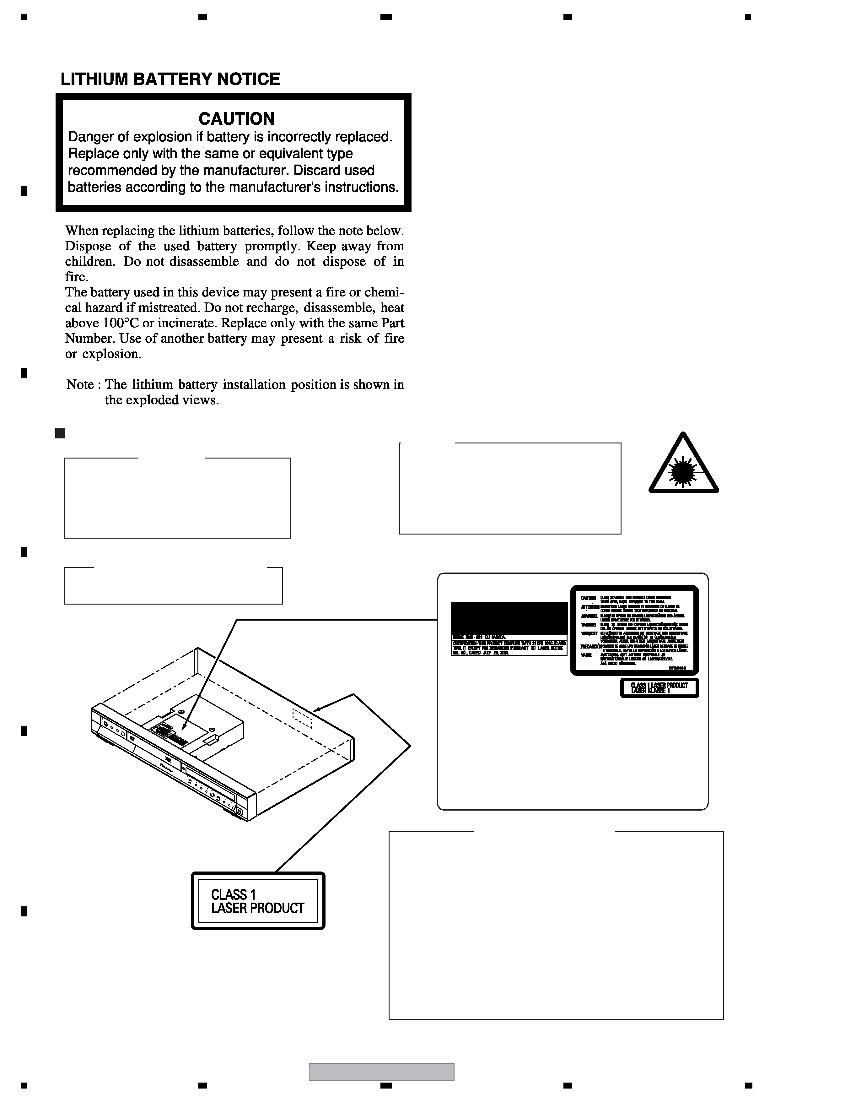
C
D
F
A
B
E
CONTENTS
SAFETY INFORMATION ..................................................................................................................................... 2
1. SPECIFICATIONS ............................................................................................................................................ 5
2. EXPLODED VIEWS AND PARTS LIST ............................................................................................................ 8
2.1 PACKING ................................................................................................................................................... 8
2.2 EXTERIOR............................................................................................................................................... 10
2.3 FRONT PANEL ........................................................................................................................................ 12
3. BLOCK DIAGRAM AND SCHEMATIC DIAGRAM ..........................................................................................14
3.1.1 OVERALL BLOCK DIAGRAM............................................................................................................... 14
3.1.2 TUNB and JCKB ASSY BLOCK DIAGRAM..........................................................................................16
3.1.3 MAIN ASSY BLOCK DIAGRAM............................................................................................................ 18
3.1.4 POWER BLOCK DIAGRAM.................................................................................................................. 20
3.2 OVERALL WIRING DIAGRAM................................................................................................................. 22
3.3 TUNB ASSY ............................................................................................................................................. 24
3.4 JCKB ASSY(1/3) ...................................................................................................................................... 26
3.5 JCKB ASSY(2/3) ...................................................................................................................................... 28
3.6 JCKB ASSY(3/3) ...................................................................................................................................... 30
3.7 MAIN ASSY(1/5) ...................................................................................................................................... 32
3.8 MAIN ASSY(2/5) ...................................................................................................................................... 34
3.9 MAIN ASSY(3/5) ...................................................................................................................................... 36
3.10 MAIN ASSY(4/5) .................................................................................................................................... 38
3.11 MAIN ASSY(5/5) .................................................................................................................................... 40
3.12 FLKY, KIRB, FRJB and DVJB ASSYS ................................................................................................... 42
3.13 SDEB ASSY........................................................................................................................................... 44
3.14 POWER SUPPLY UNIT.......................................................................................................................... 46
3.15 WAVE FORMS ....................................................................................................................................... 48
4. PCB CONNECTION DIAGRAM ..................................................................................................................... 51
4.1 TUNB ASSY ............................................................................................................................................. 52
4.2 JCKB ASSY ............................................................................................................................................. 54
4.3 MAIN ASSY ............................................................................................................................................. 58
4.4 FLKY, KIRB, FRJB and DVJB ASSYS ..................................................................................................... 62
4.5 SDEB ASSY............................................................................................................................................. 66
4.6 POWER SUPPLY UNIT............................................................................................................................ 68
5. PCB PARTS LIST ........................................................................................................................................... 69
6. ADJUSTMENT ............................................................................................................................................... 74
6.1 TUNB ASSY ADJUSTMENT.................................................................................................................... 74
6.2 MAIN ASSY ADJUSTMENT .................................................................................................................... 75
7. GENERAL INFORMATION ............................................................................................................................. 76
7.1 DIAGNOSIS ............................................................................................................................................. 76
7.1.1 CPRM ID NUMBER AND DATA SETTING............................................................................................ 77
7.1.2 MODEL SETTING................................................................................................................................. 79
7.1.3 DOWNLOAD METHOD ........................................................................................................................ 80
7.1.4 SERVICE MODE................................................................................................................................... 82
7.1.5 DV DEBUG MODE................................................................................................................................ 93
7.1.6 ERROR RATE MEASUREMENT .......................................................................................................... 96
7.1.7 VIDEO ADJUSTMENT FOR SPECIFIC AREA ..................................................................................... 98
7.1.8 AGING MODE..................................................................................................................................... 102
7.1.9 SETUP SEQUENCE ........................................................................................................................... 103
7.1.10 DISASSEMBLY ................................................................................................................................. 104
7.2 IC ........................................................................................................................................................... 108
7.3 OUTLINE OF THE PRODUCT............................................................................................................... 139
7.4 DISC/CONTENT FORMAT .................................................................................................................... 142
7.5 CLEANING............................................................................................................................................. 143
8. PANEL FACILITIES ...................................................................................................................................... 144