PIONEER DEHMG2037ZF Service Manual

Cover page of PIONEER DEHMG2037ZF Service Manual

Service Manual for PIONEER DEHMG2037ZF, downloadable as a PDF file.

Manual details

  • Immediate download after payment.
  • Delivered as a PDF file.
  • The manual has 92 pages
  • File size: 6.72 MB
  • Available language versions: English
  • Different language versions may vary sligthly in file size and page count.

We guarantee that...

  • our manuals are complete,
  • the manual includes circuit diagrams,
  • our manuals are checked with antivirus,
  • We'll issue refund if the manual is damaged, incomplete or unreadable (our refund policy)

Sample pages

Thumbnail of page 1Thumbnail of page 2Thumbnail of page 3Thumbnail of page 4
Thumbnail of page 5Thumbnail of page 6Thumbnail of page 7Thumbnail of page 8
Thumbnail of page 9
background image
PIONEER CORPORATION
4-1, Meguro 1-Chome, Meguro-ku, Tokyo 153-8654, Japan
PIONEER ELECTRONICS (USA) INC.
P.O.Box 1760, Long Beach, CA 90801-1760 U.S.A.
PIONEER EUROPE NV
Haven 1087 Keetberglaan 1, 9120 Melsele, Belgium
PIONEER ELECTRONICS ASIACENTRE PTE.LTD. 253 Alexandra Road, #04-01, Singapore 159936
C PIONEER CORPORATION 2003
K-ZZD. JUNE 2003 Printed in Japan
ORDER NO.
CRT3091
CD/MP3 6 DISC IN-DASH CHANGER WITH FM/AM TUNER
DEH-MG2037ZF
XU/UC
Service
Manual
FORD
DEH-MG2037ZF/XU/UC
VEHICLE
DESTINATION
PRODUCED AFTER
FORD PART No.
ID No. PIONEER MODEL No.
Ranger
U.S.A., CANADA
August 2003
4L5T-18C815-
DEH-MG2037ZF/XU/UC
Ranger
U.S.A., CANADA
August 2003
4L5T-18C815-
DEH-MG2137ZF/XU/UC
- This service manual should be used together with the following manual(s):
Model No.
Order No.
Mech. Module Remarks
CX-951
CRT2872
G2
CD Mech. Module:Circuit Description, Mech.Description, Disassembly
For details, refer to "Important symbols for good services".
DEH-MG2137ZF XU/UC
background image
2
1
234
12
34
F
E
D
C
B
A
DEH-MG2037ZF/XU/UC
SAFETY INFORMATION
- CD section precaution
1. Before disassembling the unit, be sure to turn off the
power. Unplugging and plugging the connectors dur-
ing power-on mode may damage the ICs inside the
unit.
2. To protect the pickup unit from electrostatic dis-
charge during servicing, take an appropriate treat-
ment (shorting-solder) by referring to "the DISAS-
SEMBLY" on page 69.
3. After replacing the pickup unit, be sure to check the
grating. (See p.63.)
This service manual is intended for qualified service technicians; it is not meant for the casual do-it-yourselfer.
Qualified technicians have the necessary test equipment and tools, and have been trained to properly and safely repair
complex products such as those covered by this manual.
Improperly performed repairs can adversely affect the safety and reliability of the product and may void the warranty.
If you are not qualified to perform the repair of this product properly and safely, you should not risk trying to do so
and refer the repair to a qualified service technician.
[ Important symbols for good services ]
In this manual, the symbols shown-below indicate that adjustments, settings or cleaning should be made securely.
When you find the procedures bearing any of the symbols, be sure to fulfill them:
2. Adjustments
To keep the original performances of the product, optimum adjustments or specification confirmation is indispensable.
In accordance with the procedures or instructions described in this manual, adjustments should be performed.
3. Cleaning
For optical pickups, tape-deck heads, lenses and mirrors used in projection monitors, and other parts requiring cleaning,
proper cleaning should be performed to restore their performances.
5. Lubricants, glues, and replacement parts
Appropriately applying grease or glue can maintain the product performances. But improper lubrication or applying
glue may lead to failures or troubles in the product. By following the instructions in this manual, be sure to apply the
prescribed grease or glue to proper portions by the appropriate amount.For replacement parts or tools, the prescribed
ones should be used.
4. Shipping mode and shipping screws
To protect the product from damages or failures that may be caused during transit, the shipping mode should be set or
the shipping screws should be installed before shipping out in accordance with this manual, if necessary.
1. Product safety
You should conform to the regulations governing the product (safety, radio and noise, and other regulations), and
should keep the safety during servicing by following the safety instructions described in this manual.
background image
3
5
6
7
8
F
E
D
C
B
A
5
6
7
8
DEH-MG2037ZF/XU/UC
CONTENTS
SAFETY INFORMATION ......................................................................................................................................................2
1. SPECIFICATIONS .................................................................................................................................................................4
2. EXPLODED VIEWS AND PARTS LIST ................................................................................................................................5
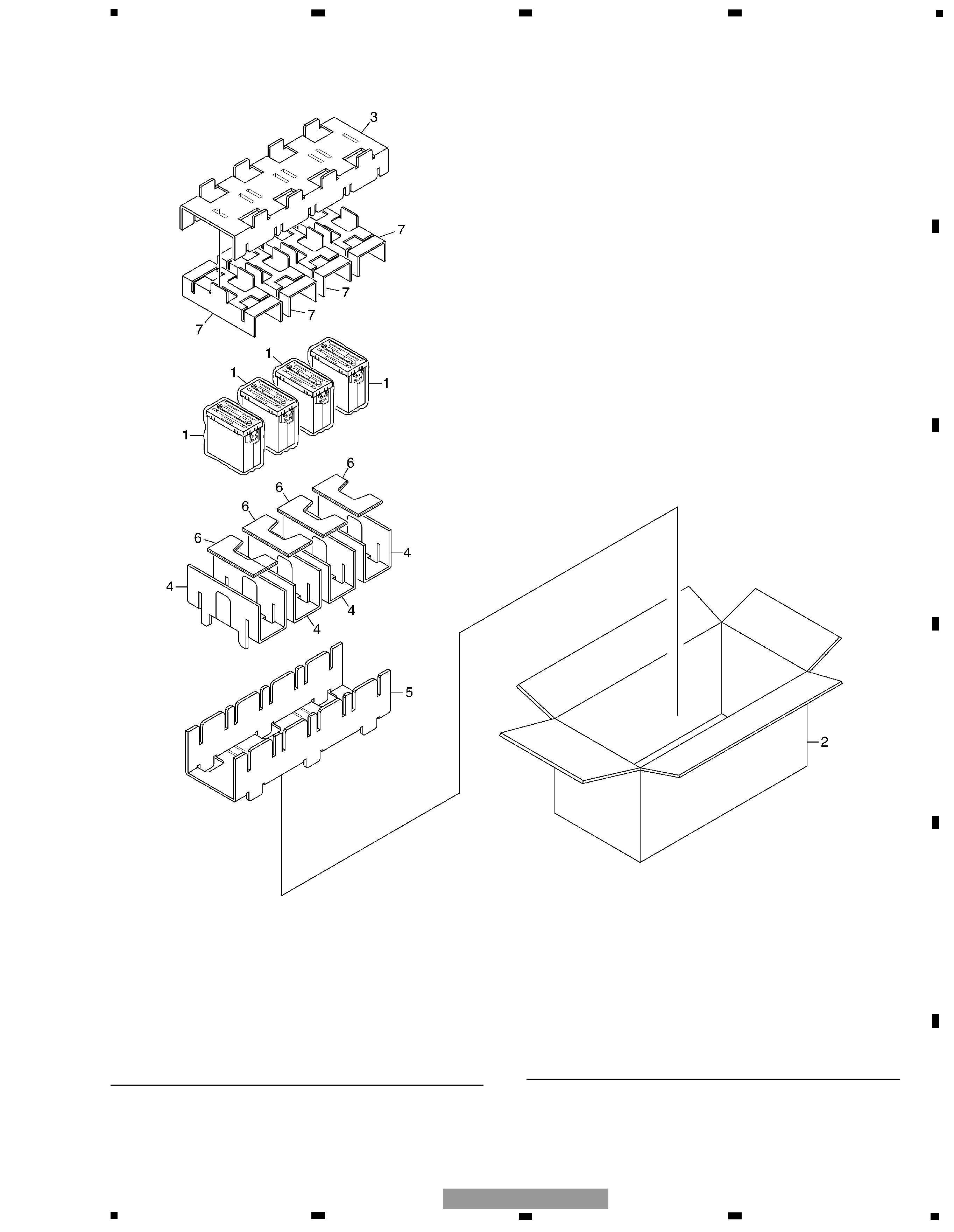
2.1 PACKING..........................................................................................................................................................................5
2.2 EXTERIOR ........................................................................................................................................................................6
2.3 MECHANISM UNIT(G2BM)(SERVICE)(1) ....................................................................................................................10
2.4 MECHANISM UNIT(G2BM)(SERVICE)(2) ....................................................................................................................12
3. BLOCK DIAGRAM AND SCHEMATIC DIAGRAM.............................................................................................................15
3.1 BLOCK DIAGRAM(1) .....................................................................................................................................................15
3.2 BLOCK DIAGRAM(2) .....................................................................................................................................................16
3.3 OVERALL CONNECTION DIAGRAM(GUIDE PAGE) ...................................................................................................18
3.4 KEYBOARD UNIT ..........................................................................................................................................................24
3.5 CD MECHANISM MODULE(GUIDE PAGE)..................................................................................................................26
3.6 TUNER RELAY UNIT .....................................................................................................................................................34
4. PCB CONNECTION DIAGRAM..........................................................................................................................................36
4.1 MOTHER UNIT ..............................................................................................................................................................36
4.2 KEYBOARD UNIT ..........................................................................................................................................................40
4.3 CD MECHANISM MODULE ..........................................................................................................................................42
4.4 TUNER RELAY UNIT .....................................................................................................................................................48
5. ELECTRICAL PARTS LIST..................................................................................................................................................49
6. ADJUSTMENT ...................................................................................................................................................................60
6.1 TEST MODE...................................................................................................................................................................60
6.2 CD ADJUSTMENT ........................................................................................................................................................61
6.3 CHECKING THE GRATING AFTER CHANGING THE PICKUP UNIT...........................................................................63
6.4 TEST MODE(CD) ...........................................................................................................................................................65
6.5 SYSTEM MICROCOMPUTER TEST PROGRAM..........................................................................................................68
7. GENERAL INFORMATION.................................................................................................................................................69
7.1 DIAGNOSIS ...................................................................................................................................................................69
7.1.1 DISASSEMBLY .......................................................................................................................................................69
7.1.2 CONNECTOR FUNCTION DESCRIPTION .............................................................................................................74
7.2 PARTS ............................................................................................................................................................................75
7.2.1 IC .............................................................................................................................................................................75
7.2.2 DISPLAY ..................................................................................................................................................................86
7.3 EXPLANATION ..............................................................................................................................................................87
7.3.1 SYSTEM BLOCK DIAGRAM ..................................................................................................................................87
7.3.2 OPERATIONAL FLOW CHART ...............................................................................................................................88
7.4 NOTES ON SERVICING ................................................................................................................................................89
7.4.1 CLEANING ..............................................................................................................................................................89
7.4.2 FACTORY SETTINGS .............................................................................................................................................89
8. OPERATIONS .....................................................................................................................................................................90
background image
4
1
234
12
34
F
E
D
C
B
A
DEH-MG2037ZF/XU/UC
1. SPECIFICATIONS
General
Power source ..............................................................................14.4V(10.5V-16.0V allowable) DC
Grounding system ......................................................................Negative type
Backup current ............................................................................3mA or less
Dimensions .................................................................................189(W) x100(H) x188(D)mm
Weight .........................................................................................2.4kg
CD player
System.........................................................................................Compact disc audio system
Usable discs ................................................................................Compact disc
Signal format ..............................................................................Sampling frequency : 44.1kHz
Number of quantization : 16;linear
S/N ...............................................................................................75dB or more
Distortion.....................................................................................0.1% or less
MP3 decoding format.................................................................MPEG1 and MPEG2 audio layer 3
FM tuner
Frequency....................................................................................87.75, 87.9-107.9 MHz
S/N 58dB or more
Distortion.....................................................................................1.5% or less
IF interference .............................................................................95dB or more
Image interference......................................................................45dB or more
Stereo Separation.......................................................................25dB or more(400Hz)
AM tuner
Frequency....................................................................................530-1710 kHz
S/N 20dB useable sensibility .....................................................33dBµ 6dB
S/N 50dB +10dB, -6dB
Distortion.....................................................................................1.0% or less
IF interference .............................................................................75dB or more
Image interference......................................................................60dB or more
background image
5
6
7
8
F
E
D
C
B
A
5
6
7
8
2. EXPLODED VIEWS AND PARTS LIST
2.1 PACKING
*
1 Polyethylene Bag
CEG1317
2 Contain Box
CHL4766
(DEH-MG2037ZF/XU/UC)
Contain Box
CHL4767
(DEH-MG2137ZF/XU/UC)
3 Protector
CHP2619
4 Protector
CHP2620
5 Protector
CHP2621
6 Protector
CHP2622
7 Protector
CHP2717
Mark No. Description
Part No.
Mark No. Description
Part No.
NOTE:
- Parts marked by "*" are generally unavailable because they are not in our Master Spare Parts List.
- Screws adjacent to
mark on the product are used for disassembly.
- For the applying amount of lubricants or glue, follow the instructions in this manual.
( In the case of no amount instructions, apply as you think it appropriate.)
- PACKING SECTION PARTS LIST
DEH-MG2037ZF/XU/UC
5

Reviews

There are no reviews of this manual yet.