PIONEER A-509R/MY Owner's Manual

Cover page of PIONEER A-509R/MY Owner's Manual

Owner's Manual for PIONEER A-509R/MY, downloadable as a PDF file.

We also have service manual to this model.

Manual details

  • Immediate download after payment.
  • Delivered as a PDF file.
  • The manual has 12 pages
  • File size: 0.18 MB
  • Available language versions: Portuguese, Swedish, French, English, Spanish, Dutch, German, Italian
  • Different language versions may vary sligthly in file size and page count.

We guarantee that...

  • our manuals are complete,
  • our manuals are checked with antivirus,
  • We'll issue refund if the manual is damaged, incomplete or unreadable (our refund policy)

Sample pages

Thumbnail of page 1Thumbnail of page 2Thumbnail of page 3Thumbnail of page 4
Thumbnail of page 5Thumbnail of page 6Thumbnail of page 7Thumbnail of page 8
Thumbnail of page 9
background image
1
<ARB7238>
IMPORTANT
FOR USE IN THE UNITED
KINGDOM
The wires in this mains lead are coloured in
accordance with the following code :
Blue
:Neutral
Brown
:Live
If the plug provided is unsuitable for your socket
outlets, the plug must be cut off and a suitable plug
fitted.
Do not connect either wire to the earth terminal of a
three pin plug.
NOTE
After replacing or changing a fuse, the fuse cover in the
plug must be replaced with a fuse cover which corre-
sponds to the colour of the insert in the base of the plug
or the word that is embossed on the base of the plug, and
the appliance must not be used without a fuse cover. If
lost, replacement fuse covers can be obtained from your
dealer.
Only 5 A fuses approved by B.S.I. or A.S.T.A. to B.S.
1362 should be used.
The cut-off plug should be disposed of and must not be
inserted into any 13 amp socket as this can result in electric
shock. The plug or adaptor or the distribution panel should be
provided with 5 amp fuse. As the colours of the wires in the
mains lead of this appliance may not correspond with coloured
markings identifying the terminals in your plug, proceed as
follows :
The wire which is coloured blue must be connected to the
terminal which is marked with the letter N or coloured black.
The wire which is coloured brown must be connected
to the terminal which is marked with the letter L or coloured
red.
The lightning flash with arrowhead symbol, within an
equilateral triangle, is intended to alert the user to the
presence of uninsulated "dangerous voltage" within the
product's enclosure that may be of sufficient magnitude to
constitute a risk of electric shock to persons.
RISK OF ELECTRIC SHOCK
DO NOT OPEN
CAUTION
IMPORTANT
CAUTION:
TO PREVENT THE RISK OF ELECTRIC SHOCK, DO NOT
REMOVE COVER (OR BACK). NO USER-SERVICEABLE
PARTS INSIDE.
REFER SERVICING TO QUALIFIED
SERVICE PERSONNEL.
Theexclamationpointwithinanequilateraltriangleisintended
to alert the user to the presence of important operating and
maintenance (servicing) instructions in the literature
accompanying the appliance.
This product complies with the Low Voltage Directive (73/23/
EEC), EMC Directives (89/336/EEC, 92/31/EEC) and CE Marking
Directive (93/68/EEC).
Thank you for buying this PIONEER product.
Please read through these operating instructions so you will know how to
operate your model properly. After you have finished reading the instruc-
tions, put them away in a safe place for future reference.
In some countries or regions, the shape of the power plug and power
outlet may sometimes differ from that shown in the explanatory draw-
ings. However, the method of connecting and operating the unit is the
same.
WARNING: TO PREVENT FIRE OR SHOCK HAZARD, DO
NOT EXPOSE THIS APPLIANCE TO RAIN OR MOISTURE.
STEREO AMPLIFIER
z¿.?/B
Î
STEREO AMPLIFIER
z¿.?/B Direct Energy MOS
STANDBY/ON
STANDBY
OFF
ON
POWER
A
SPEAKERS
B
BASS
TREBLE
PHONES
LOUDNESS
MIN
MAX
VOLUME
DIRECT/
SB MODE
BALANCE
INPUT SELECTOR
REC SELECTOR
CD
TUNER
PHONO
TAPE 2
MONITOR
CD
TUNER
OFF
SOURCE
L
R
LINE/
SB
TAPE 1/
CD-R/MD
Î
+
2
7
3
7
3
_
+
STANDBY / ON
AMP
CD
TUNER
TAPE
TAPE
SELECT
TAPE
DECK
I DECK II
CD
DISC
SELECT
STATION
TUNER
CD
TUNER PHONO
TAPE 1 TAPE 2
LINE
VOLUME
STEREO AMPLIFIER
REMOTE CONTROL UNIT
[For European model]
If the socket outlets on the associated equipment are not suitable for the plug supplied with the product the plug must be removed
and appropriate one fitted.
The cut-off plug must be disposed of as an electrical shock hazard could exist if connected to a socket outlet.
background image
2
<ARB7238>
OPERATIONS ............................................................................... 8
REMOTE CONTROL .................................................................... 9
TROUBLESHOOTING ................................................................ 11
SPECIFICATIONS ......................................................... back cover
FEATURES ................................................................................... 2
INSTALLATION ............................................................................ 2
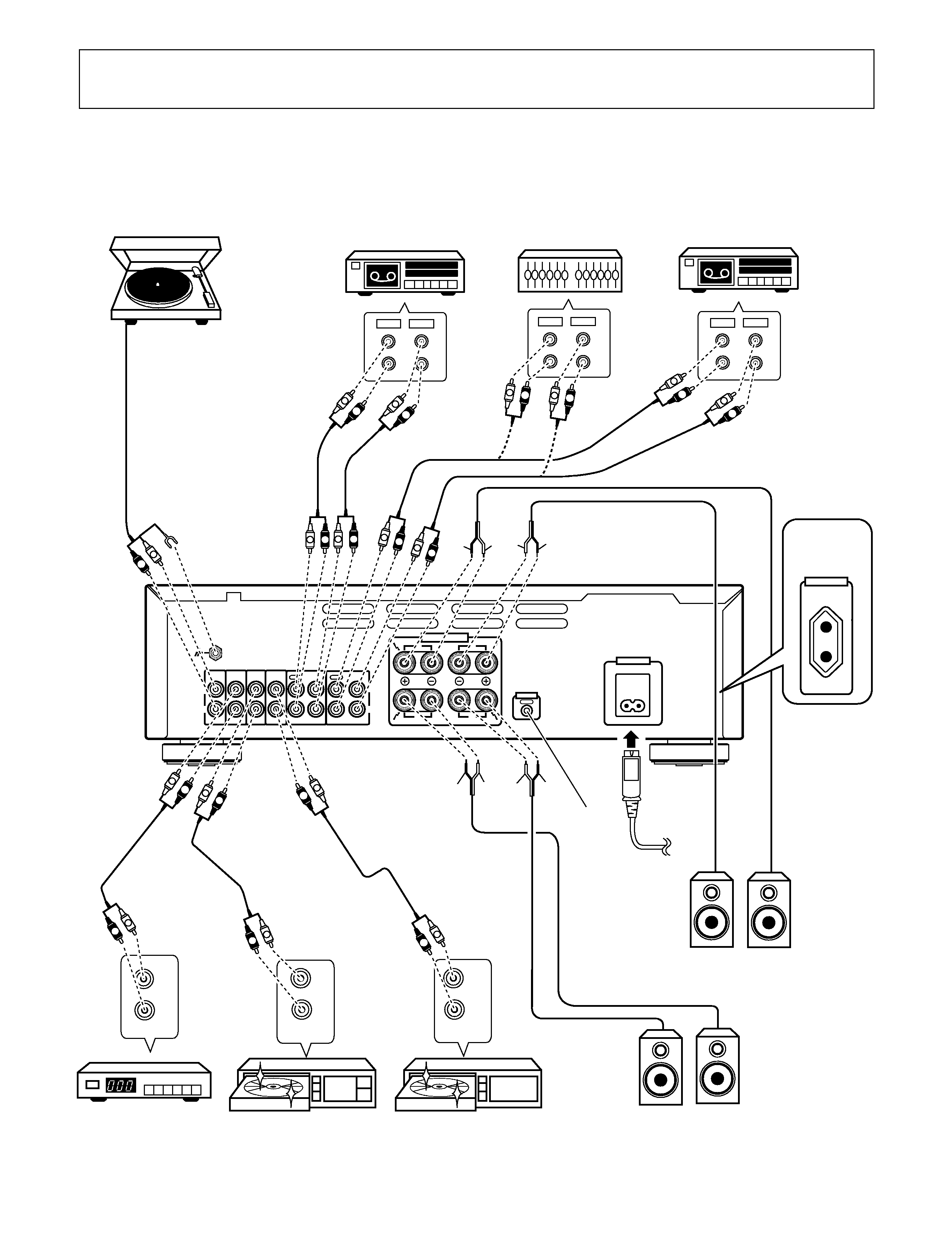
CONNECTIONS ........................................................................... 3
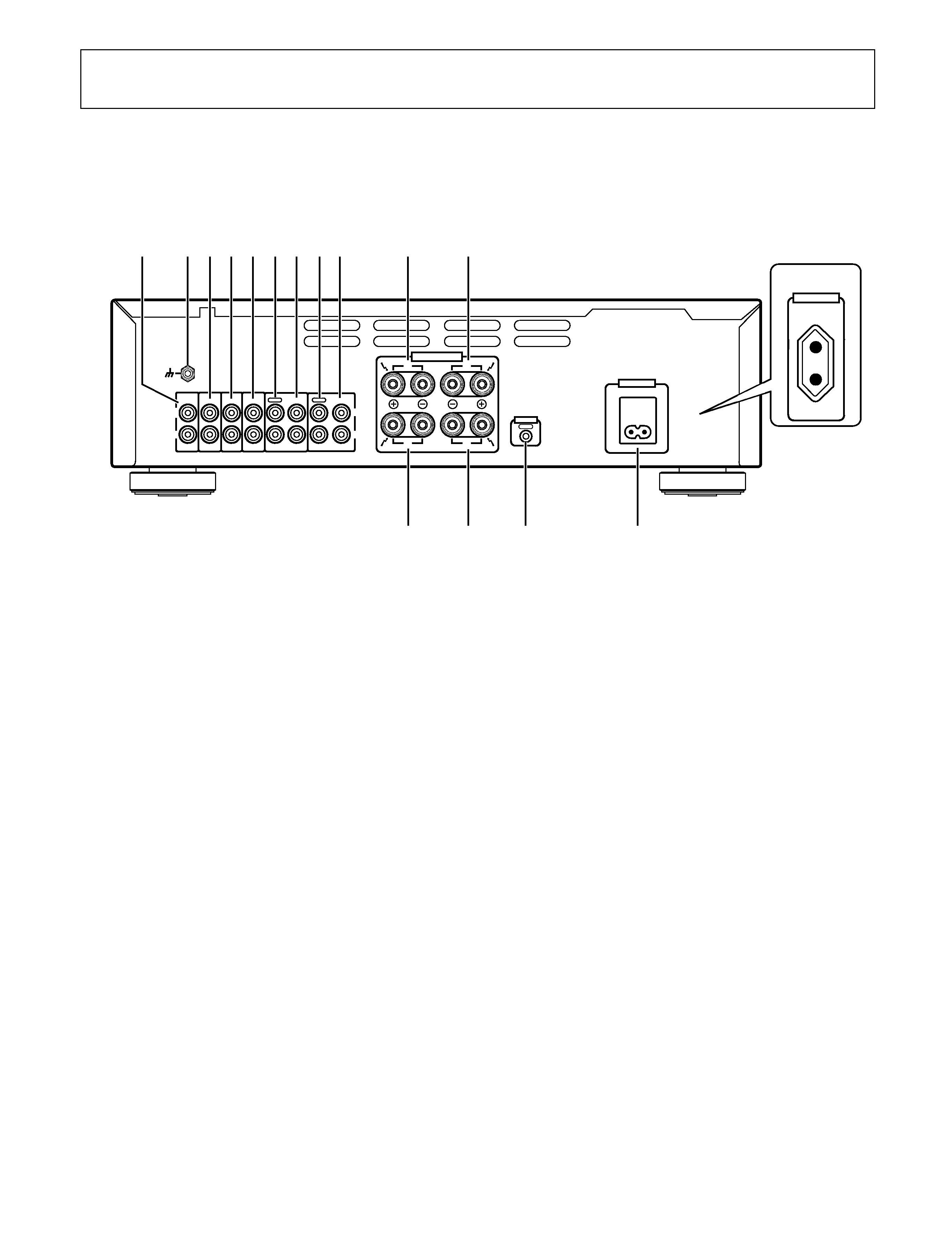
PANEL FACILITIES ...................................................................... 5
CONTENTS
FEATURES
¶ Advanced Direct Energy MOS Power Amp
Pioneer incorporates highest quality amp circuitry featuring
Advanced Direct Energy MOS FET devices which can achieve
higher performance. Together with Pioneer's original Wide
Range Linear Circuit technology they reduce power
consumption while maintaining the power output of current
models.
In terms of performance, this technology contributes to flat
damping factor characteristics across the audio spectrum. It
also allows a wide range and especially ultra high frequencies
to be reproduced more accurately and improves power
linearity.
¶ Stabilizer
Transformer stabilizer, stabilizer frame (attached to chassis)
and volume stabilizer (attached to volume knob) deliver
powerful sound.
LOCATION
Install the unit in a well-ventilated location where
it will not be exposed to high temperatures or
humidity.
Do not install the unit in a location which is exposed to direct rays
of the sun, or near hot appliances or radiators. Excessive heat
can adversely affect the cabinet and internal components. Instal-
lation of the unit in a damp or dusty environment may also result
in a malfunction or an accident. (Avoid installation near cookers
etc., where the unit may be exposed to oily smoke, steam or heat.)
Do not install the unit on a tottered stand, nor on an unstable or
inclined surface.
VENTILATION
· When installing this unit, make sure to leave space around the
unit for ventilation to improve heat radiation (at least 60 cm at
top, 10 cm at rear, and 30 cm at each side). If not enough space
is provided between the unit and walls or other equipment,
heat will build up inside, interfering with performance or
causing malfunctions.
· Do not place on a thick carpet, bed, sofa or fabric having a thick
pile. Do not cover with fabric or other covering.
Anything that blocks ventilation will cause internal temperature
to rise, which may lead to breakdown or fire hazard.
INSTALLATION
CONDENSATION
When the unit is brought into a warm room from previously cold
conditions or when the room temperature is suddenly increased,
condensation may form inside and the unit may not be able to
attain its full performance. In cases like this, allow the unit to stand
for about an hour or raise the room temperature gradually.
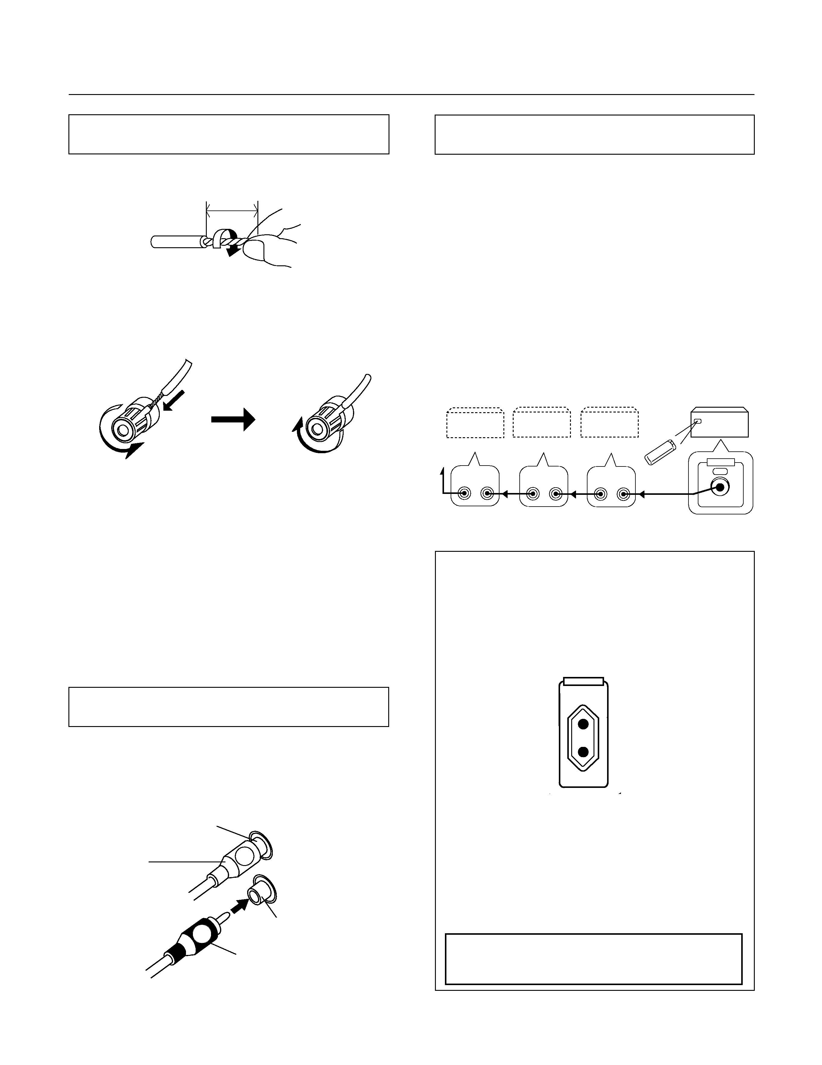
POWER-CORD CAUTION
Handle the power cord by the plug. Do not pull out the plug by
tugging the cord and never touch the power cord when your hands
are wet as this could cause a short circuit or electric shock. Do not
place the unit, a piece of furniture, etc., on the power cord, or
pinch the cord. Never make a knot in the cord or tie it with other
cords. The power cords should be routed such that they are not
likely to be stepped on. A damaged power cord can cause fire or
give you an electrical shock. Check the power cord once in a while.
When you find it damaged, ask your nearest PIONEER authorized
service center or your dealer for a replacement.
NOTES:
÷ If you use an other power cord than provided, we cannot
assume the liabilities in what may occur as a result of it.
÷ (The provided power cord has a current capacity of 2.5 A.)
¶ Designed for Low Power Consumption
This model incorporates several features for energy efficiency
to reduce power consumption.
1 Direct Energy Circuit
2 Local Off circuit: Tone Local Off, Phono Local OFF, Silent
Microcomputer
3 S-MOS: Instead of the digital transistors usually used in
logic circuits, this unit employs S-MOS devices in some
areas. These do not require base current, so they help re-
duce power consumption.
¶ Energy-Saving Design
This unit is designed to use minimal electricity when power is
switched OFF (during Standby).
Regarding the value of the power consumption in standby
mode, refer to "SPECIFICATIONS" on page 12 (back cover).
background image
3
<ARB7238>
SIGNAL
GND
PHONO
TUNER
LINE/
SURROUND
BACK
TAPE1/CD­R/MD
TAPE2 MONITOR
CD
IN
IN
IN
IN
OUT
IN
OUT
IN
REC
PLAY
REC
PLAY
L
R
L
R
R
R
L
L
B
A
SPEAKERS
CONTROL
OUT
AC INLET
FM-AM
CD
DVD
REC
PLAY
L
R
L
R
AUDIO OUT
REC
PLAY
L
R
L
R
L
R
OUTPUT
L
R
OUTPUT
L
R
L
R
L
R
L
R
L
R
L
R
L
R
L
R
L
R
L
R
L
R
L
R
IN
OUT
L
R
L
R
L
R
L
R
L
R
·
ª
ª
·
·
·
ª
ª
AC OUTLET
SWITCHED
100W MAX
CONNECTIONS
Before making or changing the connections, switch
off the power switch and disconnect the power cord
from the AC outlet.
Cassette deck/MD recorder
Adaptor
component
(graphic equalizer, etc.)
Cassette deck/
CD recorder/
MD recorder
CD player
DVD player, VCR, etc.
See page 4.
Speaker system B
(Left)
(Right)
To an AC wall socket.
Tuner
Turntable
Illustration shows U.K. model
See page 4.
European
model only
Speaker system A
(Left)
(Right)
background image
4
<ARB7238>
CONNECTIONS
By interconnecting the CONTROL jacks of Pioneer units with the
Î mark, the entire system can be operated with this remote
control unit, although some of the units (AM/FM tuner, compact
disc player, cassette deck, etc.) may not be equipped with re-
mote sensors. The entire system can be operated by the remote
control unit by connecting PIONEER stereo components to each
other using the control input (CONTROL IN) jack on each com-
ponent. Use the remote control cord supplied with the respec-
tive unit for the connection. As long as you connect "OUT" to
"IN", the connecting sequence is arbitrary. In the case of a unit
which has only an "IN" connector, however, connect it last.
1 Remote control unit
2 A-509R
3 Cassette deck
4 Compact disc player
5 AM/FM tuner
L
R
Red plug
Right channel
White plug
Left channel
Connect the white plug to the left (L) channel, and the red plug
to the right (R) channel. Be sure to push the plugs in securely.
1
3
54
2
10mm
Twist the wire core.
2. Loosen the knob and insert the wire core into the terminal
hole.
3. Tighten the knob to fix the wire core in place.
NOTE:
Do not allow any of the cord conductors to protrude from the
terminals or touch any other conductors. Malfunctioning or break-
down may occur when conductors come into contact with each
other.
Speaker Impedance
When a speaker system is connected to only SPEAKERS A or
SPEAKERS B terminals, such speakers should have a rated im-
pedance in the range of 4
to 16 .
When speaker systems are connected to both the A and B termi-
nals, they should have a rated impedance in the range of 8
to
32
.
1. Strip off the vinyl covering and twist the tip of the wire core.
European model only:
AC OUTLET
[SWITCHED TOTAL 100 W MAX]
Power supplied through this outlet is turned on and off by
the amplifier's POWER switch. Total electrical power con-
sumption of connected equipment should not exceed 100 W.
CONTROL
OUT
CONTROL
OUT
IN
CONTROL
OUT
IN
CONTROL
OUT
IN
3
2
1
NOTES:
¶ This unit should be disconnected by removing the
power plug from the wall socket when not in regular
use, e.g. when on vacation.
¶ Do not connect appliances with high power consump-
tion such as heaters, irons, or television sets to this AC
OUTLET in order to avoid overheating and fire risk. This
can also cause the receiver to malfunction.
CAUTION:
DO NOT CONNECT A MONITOR OR TV SET TO
THE AC OUTLET.
CONNECTING THE SPEAKER CORDS
CONNECTING THE INPUT/OUTPUT CORDS
REMOTE CONTROL CORD CONNECTIONS
AC OUTLET
SWITCHED
100W MAX
background image
5
<ARB7238>
SIGNAL
GND
PHONO
TUNER
LINE/
SURROUND
BACK
TAPE1/CD­R/MD
TAPE2 MONITOR
CD
IN
IN
IN
IN
OUT
IN
OUT
IN
REC
PLAY
REC
PLAY
L
R
L
R
R
R
L
L
B
A
SPEAKERS
CONTROL
OUT
AC OUTLET
SWITCHED
100W MAX
AC INLET
0 SPEAKERS B terminals (Right channel)
- SPEAKERS B terminals (Left channel)
= AC INLET jack
Connect one end of the power cord to here and the other
end to an AC wall socket, or the AC outlet of an audio timer.
If you are going to be away from home for a long period of
time, disconnect the unit from the wall socket.
~ CONTROL OUT jack (see page 4 )
This jack is for outputting control signals when operating
other components bearing the
Î mark with the amplifier's
remote control unit.
! SPEAKERS A terminals (Left channel)
@ SPEAKERS A terminals (Right channel)
# AC OUTLET (see page 4 )(European model only)
1 PHONO terminals
2 SIGNAL GND (Turntable ground) terminal
3 TUNER terminals
4 CD terminals
5 LINE/SURROUND BACK terminals
6 TAPE 1/CD-R/MD REC (OUT) terminals
7 TAPE 1/CD-R/MD PLAY (IN) terminals
8 TAPE 2 MONITOR REC (OUT) terminals
9 TAPE 2 MONITOR PLAY (IN) terminals
PANEL FACILITIES
(REAR PANEL)
@=
~
2 3 45 67 8 9
0
-
!
#
European
model only
Illustration shows U.K. model
1

Reviews

There are no reviews of this manual yet.