ONKYO TXSR8250 Service Manual

Cover page of ONKYO TXSR8250 Service Manual

Service Manual for ONKYO TXSR8250, downloadable as a PDF file.

We also have owner's manual to this model.

Manual details

  • Immediate download after payment.
  • Delivered as a PDF file.
  • The manual has 117 pages
  • File size: 9 MB
  • Available language versions: English
  • Different language versions may vary sligthly in file size and page count.

We guarantee that...

  • our manuals are complete,
  • the manual includes circuit diagrams,
  • our manuals are checked with antivirus,
  • We'll issue refund if the manual is damaged, incomplete or unreadable (our refund policy)

Sample pages

Thumbnail of page 1Thumbnail of page 2Thumbnail of page 3Thumbnail of page 4
Thumbnail of page 5Thumbnail of page 6Thumbnail of page 7Thumbnail of page 8
Thumbnail of page 9
background image
TX-SR502/E/8250/HT-R520
SERVICE MANUAL
SERVICE MANUAL
AV RECEIVER
TX-SR502 Black, Golden and Silver models
MODEL
TX-SR502
TX-SR502E
TX-SR8250
HT-R520
120V AC, 60Hz
230-240V AC, 50Hz
120V/220-230V AC, 50/60Hz
220-230V AC, 50/60Hz
MDD, MDC
MPA, MPT
MWT
MGK, MGR, MGQ
TX-SR502E Black and Silver models
230-240V AC, 50Hz
MPP
HT-R520 Black and Silver models
120V AC, 60Hz
MDD, MDC
TX-SR8250 Golden model
220-230V AC, 50/60Hz
MGR
Ref. No. 3797
042004
STANDBY/ON
PHONES
STANDBY
DISPLAY
TONE
TUNING MODE
DIGITAL INPUT
LISTENING
MODE
STEREO
MEMORY
RETURN
SETUP
VIDEO
2
TAPE
TUNER
C D
VIDEO
3
DVD
VIDEO
1
VCR
MULTI CH
SPEAKERS B
A
MASTER VOLUME
ENTER
S VIDEO
VIDEO
AUDIO
LR
VIDEO
3 INPUT
CLEAR
TUNING
PRESET
CD
+10
0
CLEAR
12
3
45
6
78
9
V1
V2
V3
DVD
MULTI CH
--/---
TAPE
TUNER
INPUT
I
+
-
ENTER
SET
UP
GUI
DE
RE
TURN
EXIT
CINE FLTR
LEVEL
-
LEVEL+
CH SEL
TEST TONE
DSP
DIRECT
STEREO
ALL ST
SURR
L NIGHT
TO
PM
ENU
MEN
U
VOL
+
-
CDR
SAT
AMP
+
_
TV
VCR
CABLE
DVD
CD
MD
DISC
CH
TONE
TUNER/
TAPE
DISPLAY
TV
INPUT
PREV
CH
DIMMER
SLEEP
RANDOM
SP A
SP B
MUTING
ANGLE
SEARCH
SUBTITLE
AUDIO
MEMORY
A-B
REPEAT
ON
STANDBY
TV
TV CH
TV VOL
RC-567M
REC
LAST M
REMOTE MODE
OPEN/CLOSEVIDEO OFF
DSP
American model
RC-567M
Others
RC-569M
SAFETY-RELATED COMPONENT
WARNING!!
COMPONENTS IDENTIFIED BY MARK
ON THE
SCHEMATIC DIAGRAM AND IN THE PARTS LIST ARE
CRITICAL FOR RISK OF FIRE AND ELECTRIC SHOCK.
REPLACE THESE COMPONENTS WITH ONKYO
PARTS WHOSE PART NUMBERS APPEAR AS SHOWN
IN THIS MANUAL.
MAKE LEAKAGE-CURRENT OR RESISTANCE
MEASUREMENTS TO DETERMINE THAT EXPOSED
PARTS ARE ACCEPTABLY INSULATED FROM THE
SUPPLY CIRCUIT BEFORE RETURNING THE
APPLIANCE TO THE CUSTOMER.
background image
SPECIFICATIONS-1
TX-SR502/502E/8250
TX-SR502/E/8250/HT-R520
Amplifier Section
Power output:
75 W (8 , 20 Hz-20 kHz, FTC)
All channels:
105 W (6 , 1 kHz, DIN)
130 W (6 , 1 kHz, EIAJ)
Dynamic power:
2 x 180 W (3 , front)
2 x 150 W (4 , front)
2 x 95 W (8 , front)
THD (total harmonic distortion):
0.08% (rated power)
Damping factor:
60 (front, 1 kHz, 8 )
Input sensitivity and impedance:
200 mV/47 k
(LINE)
Output level and impedance:
200 mV/470
(REC OUT)
Frequency response:
10 Hz­100 kHz/+1 dB, ­3 dB
(Direct mode)
Tone control:
+12 dB, -12 dB, 50 Hz (BASS)
+12 dB, -12 dB, 20,000 Hz (TREBLE)
S/N ratio (Direct mode):
100 dB (CD, IHF-A)
Speaker impedance:
6 ~
General
Power supply:
American model: AC 120 V, 60 Hz
Worldwide model: AC 220­230 V and
120 V switchable 50/60 Hz
Other models: AC 230­240 V, 50 Hz
AC 220­230 V, 50 Hz
Power consumption:
American model: 4.6 A
Other models: 370 W
Standby power consumption:
2.5 W
Dimensions (W x H x D):
17-1/8" x 5-7/8" x 14-13/16"
(435 x 150 x 376 mm)
Weight:
American, European and Australian
models: 22.5 lbs. (10.2 kg)
Asian model: 24.3 lbs. (11.0 kg)
Video Section
Input sensitivity, output level and impedance:
1.0 Vp-p/75
(component and S-Video Y)
0.7 Vp-p/75
(component PB/CB, PR/CR)
0.28 Vp-p/75
(S-Video C)
1.0 Vp-p/75
(composite)
Component video frequency response:
5 Hz­50 MHz
Tuner Section
FM
Tuning frequency range:
87.5­108.0 MHz
Usable sensitivity:
FM STEREO 17.2 dBf, 2.0
V (75 IHF)
FM MONO 11.2 dBf, 1.0
V (75 IHF)
S/N ratio:
FM STEREO 70 dB (IHF-A)
FM MONO 76 dB (IHF-A)
THD:
FM STEREO 0.3% (1 kHz)
FM MONO 0.2% (1 kHz)
FM stereo separation:
45 dB at 1 kHz
Video Inputs
Component video inputs:
2 (DVD, Video 1/2/3)
S-Video inputs:
4 (DVD, Video 1­3)
Video inputs:
4 (DVD, Video 1­3)
Video Outputs
Component video outputs:
1 (Component Video Out)
S-Video outputs:
2 (Video 1 Out, Monitor Out)
Video outputs:
2 (Video 1 Out, Monitor Out)
Audio Inputs
Digital inputs:
4 (Optical 1­3, Coaxial)
Analog inputs:
6 (CD, Tape, DVD, Video 1­3)
Multichannel analog inputs:
5.1 ch (Front L/R, Center, Surround L/R,
Subwoofer)
Audio Outputs
Analog outputs:
2 (Tape Out, Video 1 Out)
Subwoofer pre out:
1
Speaker outputs:
6+2
Phones:
1
Specifications and features are subject to change without notice.
AM
Tuning frequency range:
530­1700 kHz (American model)
522­1611 kHz (Other models)
Usable sensitivity:
30
V
S/N ratio:
40 dB
THD:
0.7%
background image
SPECIFICATIONS-2
HT-R520
TX-SR502/E/8250/HT-R520
Amplifier Section
Video Section
Tuner Section
FM
AM
General
Video Inputs
Video Outputs
Audio Inputs
Audio Outputs
Specifications and features are subject to change without notice.
Power output:
All channels:
130 W(8
, 20 Hz-20 kHz, FTC)
Dynamic power:
THD (total harmonic
distortion):
0.08% (rated power)
Damping factor:
Input sensitivity and
impedance:
200 mV/47 k
(LINE)
Output level and
impedance:
200 mV/470
(REC OUT)
Frequency response:
10 Hz-100 kHz/+1 dB, -3 dB (Direct mode)
Tone control:
±12 dB, 50 Hz (BASS)
±12 dB, 20,000 Hz (TREBLE)
S/N ratio (Direct mode):
100 dB (CD, IHF-A)
Speaker impedance:
6
Input sensitivity, output
level and impedance:
1.0 Vp-p/75 (component and S-VideoY)
Component video
frequency response:
5 Hz-50 MHz
87.5-108.0 MHz
Usable sensitivity:
FM STEREO 17.2 dBf, 2.0 µV (75
IHF)
FM MONO 11.2 dBf, 1.0 µV (75
IHF)
S/N ratio:
FM STEREO 70 dB (IHF-A)
FM MONO 76 dB (IHF-A)
THD:
FM STEREO 0.3% (1 kHz)
FM MONO 0.2% (1 kHz)
FM stereo separation:
45 dB at 1 kHz
Tuning frequency range:
530-1700 kHz
Usable sensitivity:
30 µV
S/N ratio:
40 dB
THD:
0.7%
Power supply:
Power consumption:
4.6 A
Standby power
consumption:
2.5 W
Dimensions
(W x H x D):
17-1/8" x 5-7/8" x 14-13/16"
(435 x 150 x 376 mm)
Weight:
22.5 lbs. (10.2 kg)
Component video inputs:
S-Video inputs:
Video inputs:
Component video
outputs:
S-Video outputs:
Video outputs:
Digital inputs:
4 (Optical 1-3, Coaxial)
Analog inputs:
Multichannel analog
inputs:
5.1 ch (Front L/R, Center, Surround L/R, Subwoofer)
Analog outputs:
Subwoofer pre out:
1
Speaker outputs:
6+2
Phones:
1
2 x 260 W (3
, front)
2 x 200 W (4
, front)
2 x 150 W (8
, front)
60 (front, 1 kHz, 8
)
0.7 Vp-p/75 (component PB/CB, PR/CR)
0.28 Vp-p/75 (S-Video C)
1.0 Vp-p/75 (composite)
Tuning frequency range:
AC 120 V, 60 Hz
2 (DVD, Video 1/2/3)
4 (DVD, Video 1-3)
4 (DVD, Video 1-3)
1 (Component Video Out)
2 (Video 1 Out, Monitor Out)
2 (Tape Out, Video 1 Out)
6 (CD, Tape, DVD, Video 1-3)
background image
SERVICE PROCEDURES-1
TX-SR502/E/8250/HT-R520
L
R
ANTENNA
FM
75
AM
120V
VOLTAGE
SELECTOR
220-230V
SWITCHED
100W MAX.
AC OUTLET
AV RECEIVER
MODEL NO.
TX-SR
502
OPTICAL
COAXIAL
1
2
3
DIGITAL IN
VIDEO 1
/2/3IN
R
L
SURROUND
SPEAKERS
CENTER
SPEAKER
SURROUND BACK
SPEAKER
REMOTE
CONTROL
IN
IN
IN
IN
IN
IN
IN
FRONT
SURR
CENTER
SUB
WOOFER
OUT
OUT
OUT
VIDEO 2
VIDEO 1
DVD
MONITOR
OUT
VIDEO
S VIDEO
DVD
TAPE
CD
L
R
VIDEO 2
VIDEO 1
SUBWOOFER
PRE OUT
DVD IN
COMPONENT VIDEO
Y
PB
PR
OUT
L
R
R
L
FRONT
SPEAKERS A
R
L
FRONT
SPEAKERS B
Class 2 Wiring
120V
VOLTAGE
SELECTOR
220-230V
1. Replacing the fuses
This symbol located near the fuse indicates that the
fuse used is show operating type, For continued protection against
fire hazard, replace with same type fuse, For fuse rating, refer to
the marking adjacent to the symbol.
Ce symbole indique que le fusible utilise est e lent.
Pour une protection permanente, n'utiliser que des fusibles de meme
type. Ce demier est indique la qu le present symbol est apposre.
3. To initialize the unit
[NOTE]
<DD> : USA model only
<DC> : Canadian model only
<WT> : World wide model only
<GK> : Korean model only for 220V
<GR> : Chinese model only for 220V
<PP> : European model only for 230V
<PA> : Australian model only for230V
<PT> : Asian model only for 230V
This device employs a microprocessor to perform various
functions and operations. If interference generated by an external
power supply, radio wave, or other electrical sauce results in accident
which causes the specified operations and functions to operate
abnormally.
To perform a result, please follow the procedure below.
1. Press and the hold down the VIDEO 1 button, then press the
STANDBY/ON button when the unit is Power ON.
2. After "Clear " is displayed, the preset memory and each mode
stored in the memory, are initialized and will return to the
factory settings.
REF NO.
PART NO.
DESCRIPTION
NOTES
F6901, F6902
F6901, F6902
F6901 or, F6902 or
F901
F901 or
F902
F902 or
F902 or
F903
F903 or
F903
F903 or
F903 or
252199
252100
252307
252166
252260
252076
252242
252276
252164
252258
252075
252241
252275
10A-UL
10A-EAK
FUSE
10A-TL250V
6.3A-UL/T-237
6.3A-T/UL-ST2
3.15A-SE-EAK FUSE
3.15A-SE-TL250V
3.15A-SE-TL250V
5A-UL/T-237
5A-T/UL-ST2
2.5A-SE-EAK FUSE
2.5A-SE-TL250V
2.5A-SE-TL250V
DC, DD
GK, GQ, GR, PA, PP, PT, WT
DC, DD, GR, WT
DC, DD, GR, WT
GK, GQ, GR, PA, PP, PT, WT
DC, DD
DC, DD
GK, GQ, GR, PA, PP, PT, WT
2. Safety-check out
(Only U.S.A. model)
After correcting the original service problem perform the
following safety check before releasing the set to the customer
Connect the insulating-resistance tester between the plug of
power supply cord and terminal GND on the back panel.
Specifications: More than 10Mohm at 500V
The TX-SR502/TX-SR502E uses a battery-less memory
backup system in order to retain radio presets and
other settings when it's unplugged or in the case of a
power failure. Although no batteries are required, the
TX-SR502/TX-SR502E must be plugged into an AC
outlet in order to charge the backup system.
(On non-American models, the TX-SR502/
TX-SR502E's POWER switch must be set to ON in
order to charge the backup system.) Once it has been
charged, the TX-SR502/TX-SR502E will retain the settings
for several weeks, although this depends on the
environment and will be shorter in humid climates.
5. Memory backup
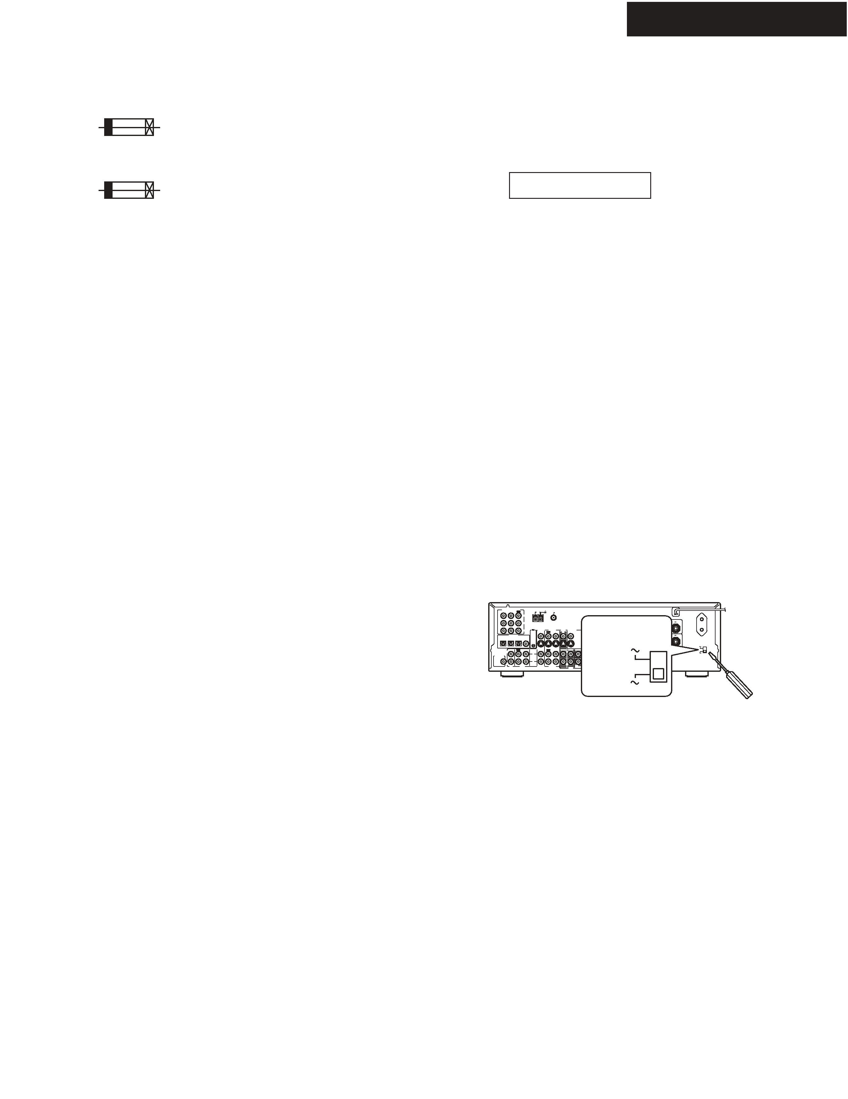
6. Setting the voltage selector
(Worldwide models only)
The Worldwide model has a voltage selector for compatibility with power
systems around the world. Before you plug in this model, make sure that
the voltage selector is set to the correct voltage for your area. If it isn't,
use a small screwdriver to set it as appropriate. For example, if the voltage
in your area is 120 volts, set the selector to "120V. " If it's between
220 and 230 volts, set it to "220-230V. "
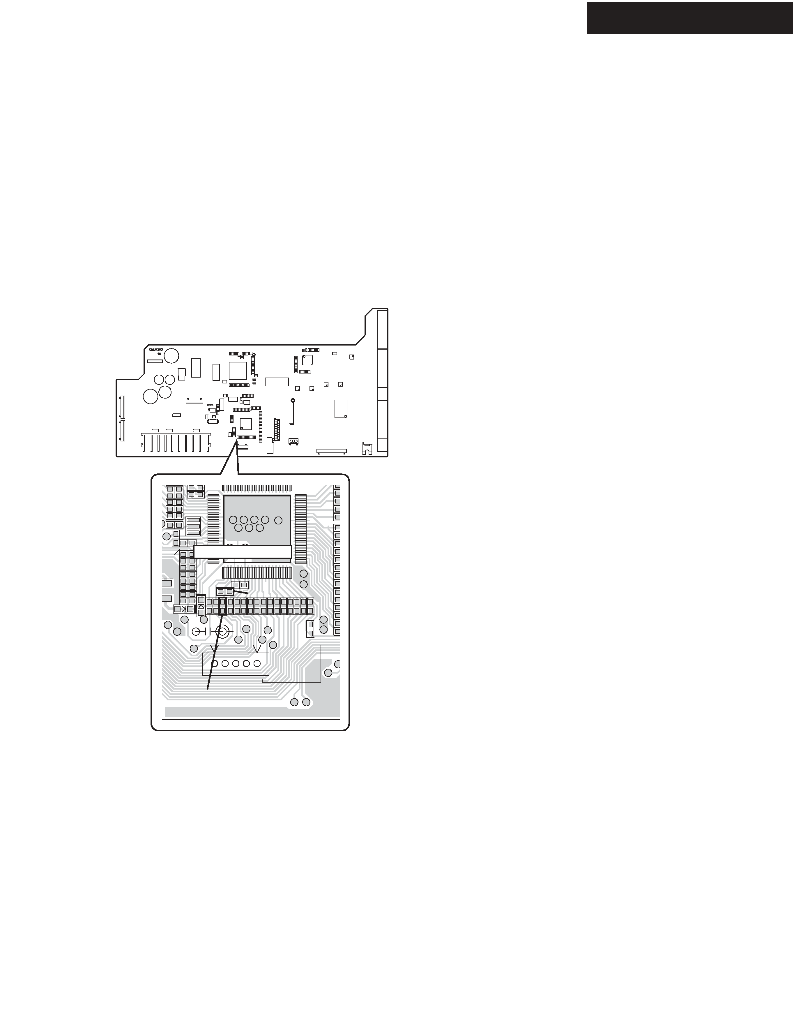
Main microprocessor Q7008.
1. Press and the hold down the DISPLAY button , then press the
STANDBY/ON button when the unit is Power ON.
Version is displayed on FL display only for 3 seconds.
2. Press the STANDBY/ON button to Power Off.
Sub microprocessor Q7502.
Check is impossible. (Unnecessary)
4. How to check version of microprocessor?
Version 04215A
ex.
background image
SERVICE PROCEDURES-2
TX-SR502/E/8250/HT-R520
NCDG-8230
25138230B
GND
232RXD
232TXD
NC
FVCC
C7002
C7003
D7001
P7701
Q7008
Q7008
R7001
R7002
R7003
R7004 R7005 R7008 R7009 R7010 R7011 R7012 R7014 R7015 R7016 R7017
R7018
R7019
R7020
R7120
Main microprocessor
7. Changing the AM band step
1. Worldwide model (MWT).
You can select AM band step 9kHz or 10kHz by the following
operation.
How to select?
Press and hold down the TUNER , then press the MEMORY.
2. Except worldwide model.
2-1. Necessary to change as follows.
R7003
Change to 10 kohms. (Refer to Fig-1)
R7004
Change to 10 kohms. (Refer to Fig-1)
2-2. How to select?
Press and hold down the TUNER , then press the MEMORY.
Fig-1
NADG-8230 (PREAMPLIFIER PC BOARD)
component side

Reviews

There are no reviews of this manual yet.