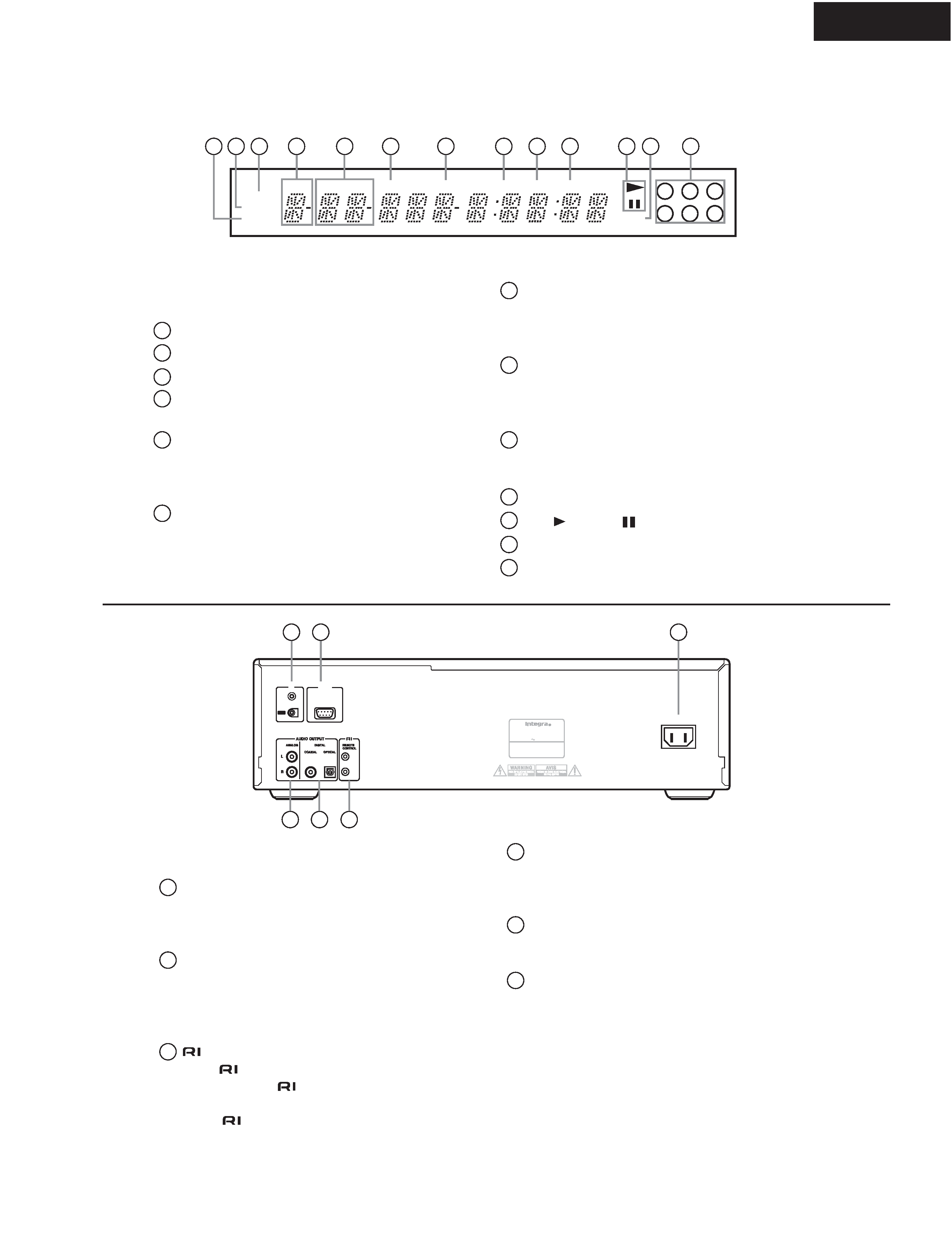
ONKYO CDC3.4 Service Manual

Cover page of ONKYO CDC3.4 Service Manual

Service Manual for ONKYO CDC3.4, downloadable as a PDF file.

We also have owner's manual to this model.

Manual details

  • Immediate download after payment.
  • Delivered as a PDF file.
  • The manual has 64 pages
  • File size: 3.14 MB
  • Available language versions: English
  • Different language versions may vary sligthly in file size and page count.

We guarantee that...

  • our manuals are complete,
  • the manual includes circuit diagrams,
  • our manuals are checked with antivirus,
  • We'll issue refund if the manual is damaged, incomplete or unreadable (our refund policy)

Sample pages

Thumbnail of page 1Thumbnail of page 2Thumbnail of page 3Thumbnail of page 4
Thumbnail of page 5Thumbnail of page 6Thumbnail of page 7Thumbnail of page 8
Thumbnail of page 9
background image
CDC-3.4
SERVICE MANUAL
SERVICE MANUAL
COMPACT DISC CHANGER
Black model
MODEL
CDC-3.4
120V AC, 60Hz
BMDD
Ref. No. 3783
Oct, 2003
RC-553C
SAFETY-RELATED COMPONENT
WARNING!!
COMPONENTS IDENTIFIED BY MARK
ON THE
SCHEMATIC DIAGRAM AND IN THE PARTS LIST ARE
CRITICAL FOR RISK OF FIRE AND ELECTRIC SHOCK.
REPLACE THESE COMPONENTS WITH ONKYO
PARTS WHOSE PART NUMBERS APPEAR AS SHOWN
IN THIS MANUAL.
MAKE LEAKAGE-CURRENT OR RESISTANCE
MEASUREMENTS TO DETERMINE THAT EXPOSED
PARTS ARE ACCEPTABLY INSULATED FROM THE
SUPPLY CIRCUIT BEFORE RETURNING THE
APPLIANCE TO THE CUSTOMER.
background image
CDC-3.4
SPECIFICATION
CDC-3.4 (Compact Disc Changer)
Signal readout system ...................... Optical non-contact
Frequency response ................................... 5 Hz-20 kHz
SN ratio ................................................................. 98 dB
Audio Dynamic range ........................................... 96 dB
THD (Total harmonic distortion) ...... 0.005% (at 1 kHz)
Audio output (Digital/Optical) ...................... -22.5 dBm
Audio output/Impedance (Digital/Coaxial) ..... 0.5 V (p-p) / 75 ohm
Audio output/Impedance (Analog) .................2.0 V (rms) / 470 ohm
Power supply rating..............................AC 120 V 60 Hz
Power consumption ................................................ 10 W
Standby power consumption .................................... 4 W
Dimensions (WxHxD).......17-1/8" x 5-3/16" x 17-3/16" (435 x 131 x 436 mm)
Weight ................................................. 15.0 lbs. (6.8 kg)
Operating conditions Temperature/Humidity........ 41-95 F (5 -35 C) / 25-80%
Disc compatibility
CD, CD-R, CD-RW
RC-553C (Remote Controller)
Transmitter .........................................................Infrared
Signal range.............................. Approx. 16 ft., 5 meters
Power supply ............Two (AA/R6) batteries (1.5 V x 2)
Specifications and features are subject to change without notice.
...........................
background image
CDC-3.4
SERVICE PROCEDURES
PROTECTION OF EYES FROM LASER BEAM DURING SERVICING
This set employs a laser. Therefore, be sure to follow
carefully the instructions below when servicing.
WARNING!!
SERVICE WARNING : DO NOT APPROACH THE
LASER EXIT WITH THE EYE TOO CLOSELY.
IN CASE IT IS NECESSARY TO CONFIRM LASER
BEAM EMISSION, BE SURE TO OBSERVE FROM
A DISTANCE OF MORE THAN 30cm FROM THE
SURFACE OF THE OBJECTIVE LENS ON THE
OPTICAL PICKUP BLOCK.
Laser Diode Properties
Material: GaAS/GaAlAs
Wavelength: 780nm
Laser output: max. 0.5mW*
Emission Duration: continuous
*This output is the value measured at a distance about 1.8mm
from the objective lens surface on the Optical Pickup Block.
LASER WARNING LABEL
The labels shown below are affixed.
DANGER:
INVISIBLE LASER RADIATION WHEN OPEN AND
INTERLOCK FAILED OR DEFEATED. AVOID DIRECT
EXPOSURE TO BEAM.
CAUTION:
HAZARDOUS LASER AND ELECTROMAGNETIC
RADIATION WHEN OPEN AND INTERLOCK DEFEATED.
ATTENTION:
RAYONNEMENT LASER ET ELECTROMAGNETIQUE
DANGEREUX SI OUVERT AVEC L'ECLENCHEMENT
DE SECURITE ANNULE.
Safety check out
After correcting the original service problem perform
the following safety check before releasing the set
to the customer.
Connect the insulating-resistance tester between the
plug of power supply cord and terminal GND on the
back panel.
Specifications: More than 10 M ohm at 500V.
(Only U.S.A. model)
Warning label
Initializing the unit
Press "STOP" key and "STANDBY" key at same time.
Displayed "INITIALIZE" on the FL display.
background image
CDC-3.4
PANEL VIEW-1
Standby/On button
This button is used to set the CDC-3.4 to On or
Standby.
Standby indicator
This indicator lights up when the CDC-3.4 is
in Standby mode.
Repeat button
This button is used with the Repeat function.
Random button
This button is used with the Random function.
Dimmer button
This button is used to adjust the display brightness.
Display button
This button is used to display elapsed, remaining,
and total time information about the current disc or
track and various information about MP3 tracks.
Remote control sensor
This sensor receives control signals from the remote
controller.
Open/Close button
This button is used to open and close the disc tray.
Disc Select buttons
These buttons are used to select discs. Playback
starts automatically when a disc is selected with one
of these buttons.
Play/pause button
This button is used to start and pause playback.
Stop button
This button is used to stop playback.
[
]/[
] & Folder
[]/[] buttons
These buttons are used to select the previous and
next tracks and to navigate folders on MP3 discs.
[
]/[
] & Folder
[]/[] buttons
These buttons are used for fast reverse and fast
forward and to navigate folders on MP3 discs.
Disc Skip button
This button is used to turn the disc tray when
loading or removing discs and to select discs for play-
back.
Disc tray light
This light illuminates the disc tray. It comes on
when the CDC-3.4 is turned on and gets brighter
when the disc tray is open.
Display
Disc tray
FRONT PANEL
1
2
3
4
5
6
7
8
9
10
11
12
13
14
15
1
2
3
4
5
6
7
8
9
10
11
12
13
14
15
background image
RANDOM indicator
MEMORY indicator
REPEAT indicator
DISC indicator
The number of the current disc appears here.
FLDR (FOLDER) indicator
While stopped, the total number of folders on the
current MP3 disc are displayed. During playback,
the number of the current folder is displayed.
NEXT indicator
This indicator appears when using
the Next Selection function.
TRACK indicator
While stopped, the total number of tracks on the
current disc are displayed. During playback, the
number of the current track is displayed.
NAME indicator
This indicator appears when the current disc is an
MP3 disc and a name (disc, folder, track) is
being displayed.
TOTAL indicator
This indicator appears when the total remain
time is displayed.
REMAIN indicator
Play
/ Pause
indicator
MP3 indicator
Disc indicators 1-6
TRACK
NEXT
TOTAL
DISC
MP
3
3
6
2
5
1
4
FLDR
REPEAT
MEMORY
RANDOM
REMAIN
NAME
1
2
3
4
5
6
7
8
9
10
11 12
13
1
2
3
4
5
6
7
8
9
10
11
12
13
FL DISPLAY
ANALOG AUDIO OUTPUT
These RCA/phono connectors can be connected to
the analog audio inputs on a hi-Þ amp or AV
receiver.
COAXIAL & OPTICAL DIGITAL AUDIO
OUTPUT
These connectors can be used to connect a CD-R,
MiniDisc, DAT recorder, digital amp, or other
equipment with digital inputs.
REMOTE CONTROL
These
(Remote Interactive) connectors can be
connected to the
connectors on your other
Integra/Onkyo AV components for interactive control.
To use
you must also make analog audio con-
nections (RCA/phono) between the CDC-3.4 and
your other Integra/Onkyo equipment.
AC INLET
The supplied power cord is connected here. The
other end of the power cord should be connected to
a suitable wall outlet.
RS 232
This RS-232 port can be connected to an external
controller.
IR IN/OUT
The IR IN connector can be used to connect a com-
mercially available IR receiver, which can be used
to pickup signals from the remote controller when
the CDC-3.4 is located in another room, installed in
a rack, or is out of range of the remote controller.
The IR OUT connector can be used to connect a
commercially available IR emitter, which can be
used to pass remote controller signals received by
the IR IN along to other AV components.
IR
OUT
IN
MODEL NO.
CDC-
3.4
2-1, NISSHIN-CHO, NEYAGAWA-SHI, OSAKA,
JAPAN
MADE IN CHINA
COMPACT DISC CHANGER
Integra Division of
ONKYO CORPORATION
RATING:
AC 120V
60 Hz
10W
RS
232
AC INLET
1
2
3
4
5
6
1
2
3
4
5
6
REAR PANEL
CDC-3.4
PANEL VIEW-2

Reviews

There are no reviews of this manual yet.