AMPLIFIER SECTION
Continuous Average Power output (FTC)
All channels:
65 watts per channel min. RMS at 8 ohms,
2 channels driven from 20 Hz to 20 kHz
with no more than 0.08% total harmonic
distortion.
Continuous Power output (DIN)85 watts 5 at 6 ohms
Maximum Power output (EIAJ) 115 watts 5 at 6 ohms
Dynamic power output:
160 watts 2 at 3 ohms
125 watts 2 at 4 ohms
85 watts 2 at 8 ohms
Total Harmonic Distortion:
0.08% at rated power
0.08% at 1 watt output
IM Distortion:
0.08% at rated power
0.08% at 1 watt output
Damping Factor:
60 at 8 ohms
Input Sensitivity and Impedance
DIGITAL INPUT (OPTICAL 1, 2): 0.5 Vp-p, 75 ohms
DIGITAL INPUT (COAXIAL): 0.5 Vp-p, 75 ohms
LINE (CD, VIDEO 1, 2, 3, TAPE): 200 mV, 50 kohms
Multichannel Input
(DVD FRONT L/C/R, SURR L/R): 200 mV, 50 kohms
(SUBWOOFER):
36 mV, 50 kohms
Output Level and Impedance
Rec out (TAPE, VIDEO 1): 200 mV, 470 ohms
Pre out (SUBWOOFER):
1 V, 470 ohms
Frequency Response:
10 Hz to 10 kHz, +1/ -3 dB (Direct mode)
Tone Control
Bass:
±12 dB at 50 Hz
Treble:
±12 dB at 20 kHz
Signal-to-Noise Ratio:
CD/TAPE: 100 dB (IHF-A, Direct mode)
Muting:
-50 dB
VIDEO SECTION
Input Sensitivity and Impedance
VIDEO (DVD, VIDEO 1, 2, 3): 1 Vp-p, 75 ohms
S VIDEO (DVD, VIDEO 1, 2, 3):1 Vp-p, 75 ohms (Y)
0.28 Vp-p, 75 ohms (C)
Output Level and Impedance
VIDEO (VIDEO 1, 2, MONITOR): 1 Vp-p, 75 ohms
S VIDEO (VIDEO 1, 2, MONITOR): 1 Vp-p, 75 ohms (Y)
0.28 Vp-p, 75 ohms (C)
TUNER SECTION
FM
Tuning Range:
87.5-108.0 MHz (50 kHz steps)
Usable Sensitivity
Mono:
11.2 dBf, 1.0 µV (75 ohms, IHF)
11.2 dBf, 0.9 µV (75 ohms, DIN)
Stereo:
17.2 dBf, 2.0 µV (75 ohms, IHF)
17.2 dBf, 23 µV (75 ohms DIN)
50 dB Quieting Sensitivity
Mono:
17.2 dBf, 2.0 µV (75 ohms)
Stereo:
37.2 dBf, 20.0 µV (75 ohms)
Capture Ratio:
2.0 dB
Image Rejection Ratio
North American models:
40 dB
Other models:
85 dB
IF Rejection Ratio:
90 dB
Signal-to-Noise Ratio
Mono:
76 dB, IHF
Stereo:
70 dB, IHF
Alternate Channel Attenuation: 55 dB, IHF, ±400 kHz
Selectivity:
50 dB (DIN)
AM Suppression Ratio:
50 dB
Total Harmonic Distortion
Mono:
0.2%
Stereo:
0.3%
Frequency Response:
30 Hz-15 kHz, ±1.0 dB
Stereo Separation:
45 dB at 1 kHz
30 dB at 100 Hz-10 kHz
AM
Tuning Range
North American models:
530-1,710 kHz (10 kHz steps)
European & Australian models: 522-1,611 kHz (9 kHz steps)
Worldwide models:
531-1,602 kHz (9 kHz steps),
530-1,710 kHz (10 kHz steps)
Usable Sensitivity:
30 µV
Image Rejection Ratio:
40 dB
IF Rejection Ratio:
40 dB
Signal-to-Noise Ratio:
40 dB
Total Harmonic Distortion:
0.7%
GENERAL
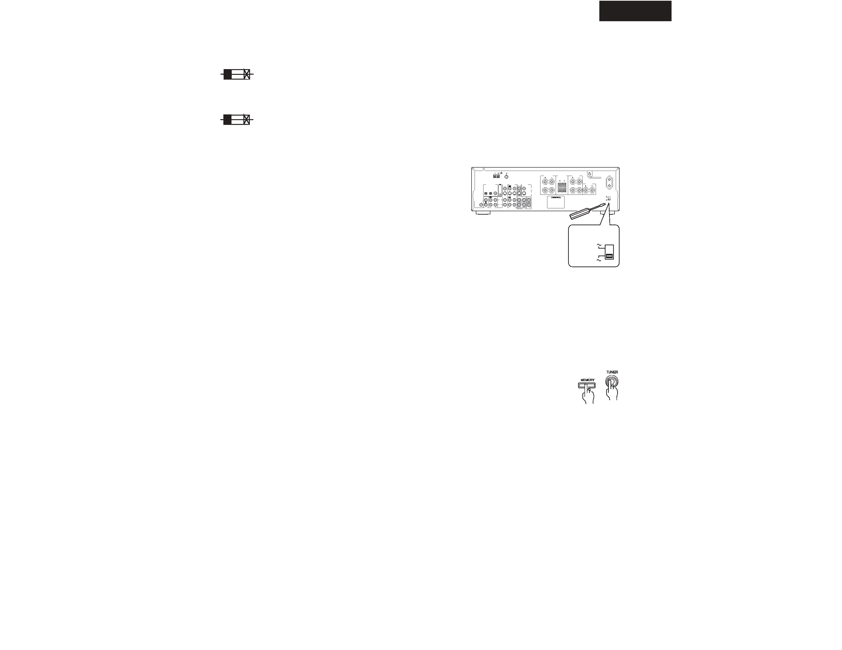
Power Supply and
Power Consumption:
AC 120 V, 60 Hz
4.0 A
AC 230-240 V, 50 Hz
320 W
AC 220-230 V and 120 V
switchable, 50/60 Hz 320 W
Dimensions (W H D):
17-1/8"
5-7/8"
14-13/16"
435
150 376 mm
Weight
North American models:
18.7 lbs., 8.5 kg
Other models:
19.4 lbs., 8.8 kg
REMOTE CONTROL
Transmitter:
Infrared
Signal range:
Approx. 16 ft., 5 meters
Power supply:
Two " AA " batteries (1.5 V
2)
Specifications and features are subject to change without notice.
Power supply and voltage vary depending on the area in which
the unit is purchased.
TX-SR500/E
SPECIFICATIONS
2