KRF-V5010/V6010/V7010/VR-205/206/207/255/257
DISC SKIP
A/B
+100
1230
456
+10
789
VIDEO 1
MD/TAPE
TUNER
CD
PHONO
BASS BOOST
BAND
VIDEO2/MON. DVD/6CH INPUT
DIRECT
SOURCE
TUNING
P.CALL
POWER
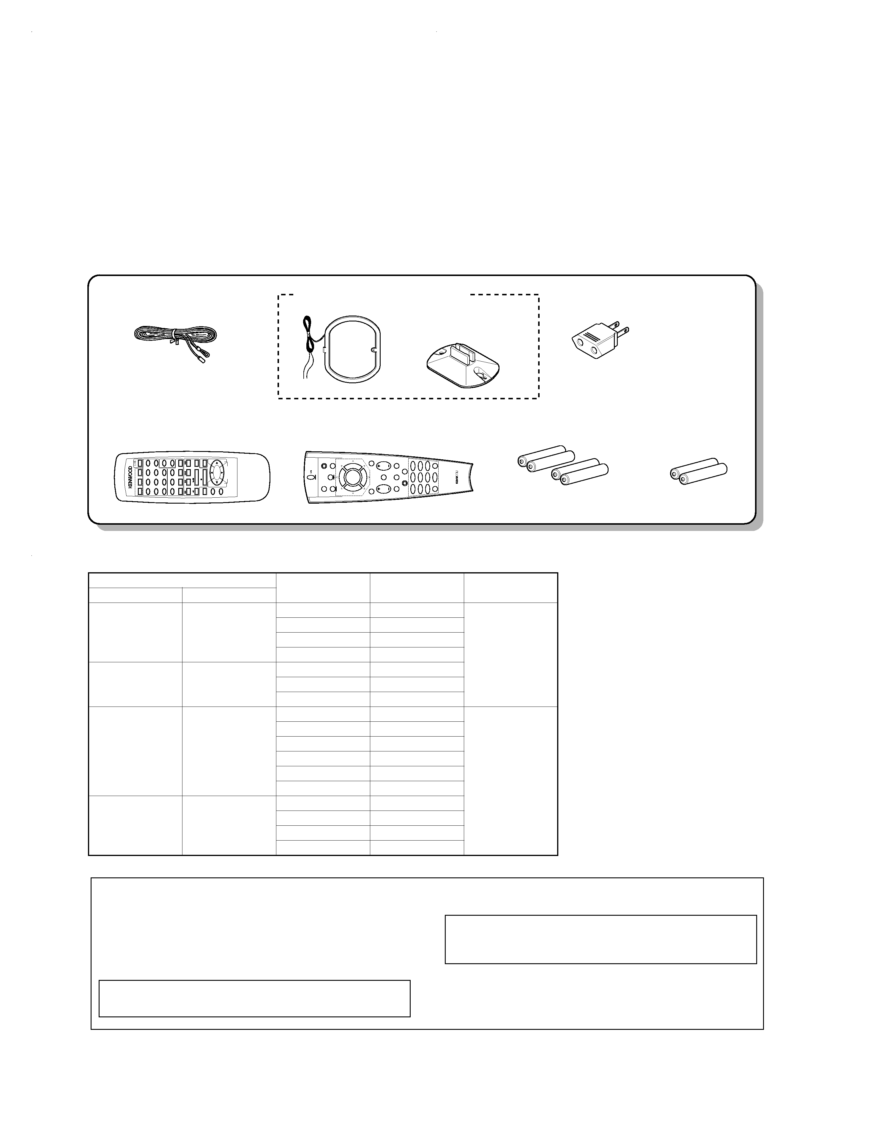
REMOTE CONTROL UNIT
RC-R0407
AUTO
VOLUME UP
VOLUME DOWN
MULTI CONTROL
MUTE
SOUND
SETUP
MODE
LISTEN
UP
DOWN
1
2
3
4
5
6
0
8
9
7
!
@
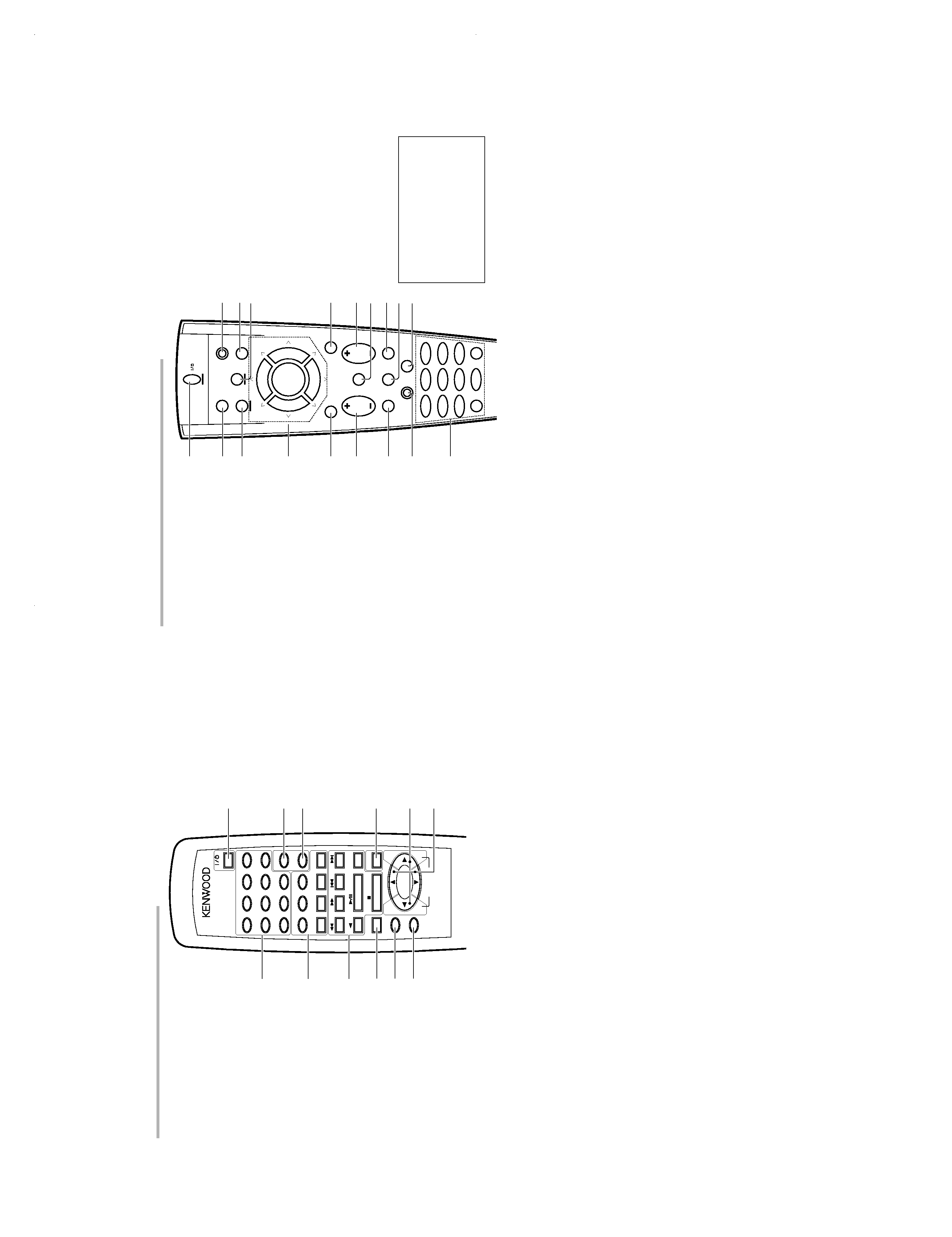
Remote control unit (RC-R0407)
2 key
If tape is selected as the input source, this
key functions as the play key for side B of
the cassette (the side facing away from the
front of the deck).
BAND (
6) key
If tuner is selected as the input source, this
key functions as the band selector key.
If CD is selected as the input source, this
key functions as the play/pause key.
If MD is selected as the input source, this
key functions as the play key.
DISC SKIP, A/B, +100 key
If CD is selected as the input source, this
key functions as the multi-CD player disc
skip key.
If TAPE is selected as the input source, this
key is used to switch between the two
decks (A and B) of a double cassette
deck.
AUTO key
If tuner is selected as the input source, this
key functions as the AUTO key.
If CD or MD is selected as the input source,
this key functions as the stop key.
4 LISTEN MODE key
Use to select the listening mode.
5 SOUND key
Use to adjust the sound quality and ambi-
ence effects.
6 SETUP key
Use to select the surround sound settings.
7 POWER key
Use to switch the power ON/STANDBY
when the POWER is turned ON.
8 BASS BOOST key
Use to select the maximum adjustment
setting for the low frequency range.
9 SOURCE DIRECT key
0 MUTE key
Use to temporarily mute the sound.
! MULTI CONTROL key
Used to make a variety of settings.
@ VOLUME CONTROL key
1 Numeric keys
If CD or MD is selected as the input source,
these keys function as numeric keys. If
tuner is selected as the input source, these
keys are used to call up station presets.
2 Input selector keys
Use to select the receiver's input source.
3 Component operation keys
Use these keys to operate other compo-
nents with system control connections to
the receiver.
TUNING (
1 ¡) keys
If tuner is selected as the input source,
these keys function as tuning keys.
If CD or MD is selected as the input source,
these keys function as search keys.
P.CALL (
4 ¢) keys
If tuner is selected as the input source,
these keys function as P.CALL keys.
If CD or MD is selected as the input source,
these keys function as skip keys.
4
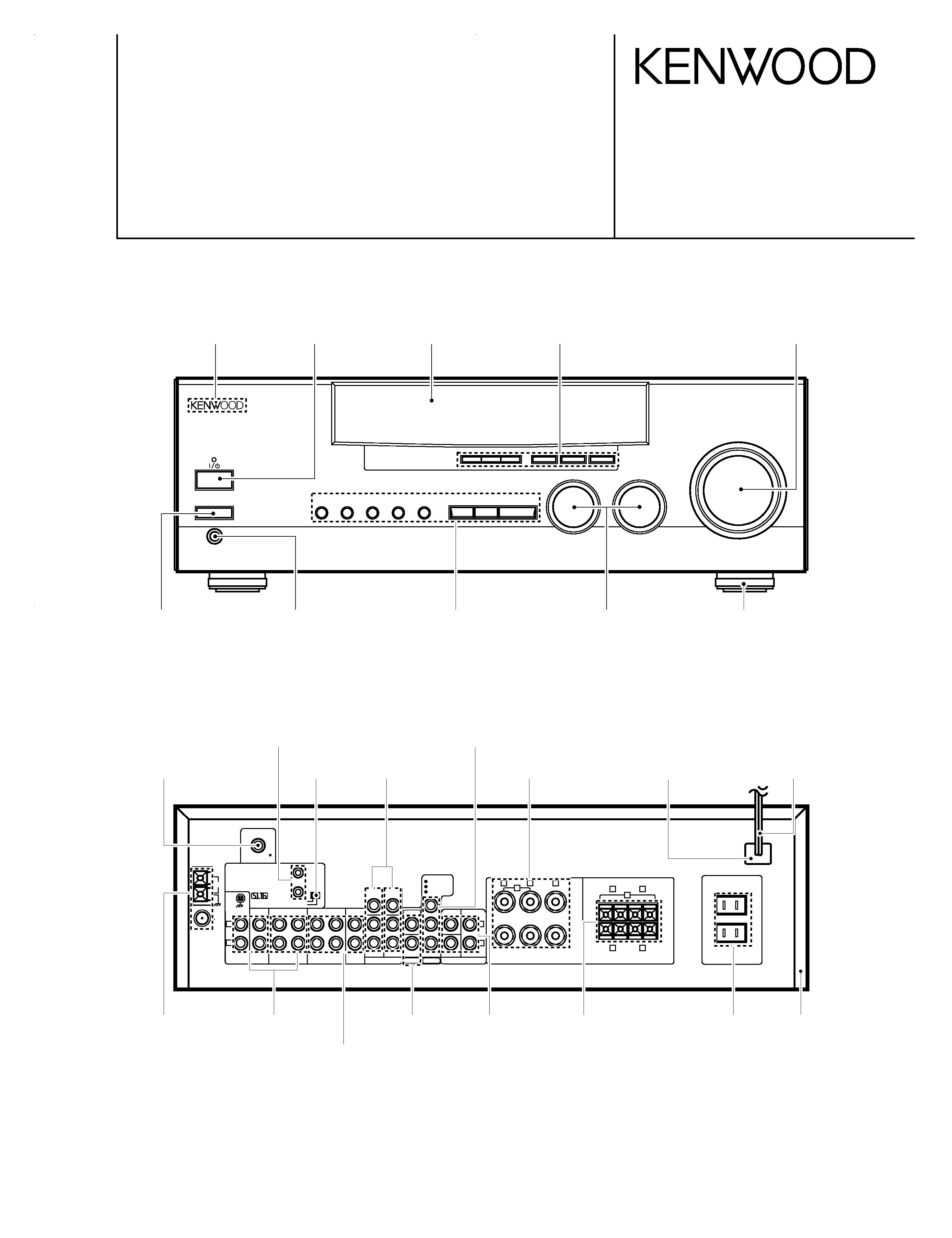
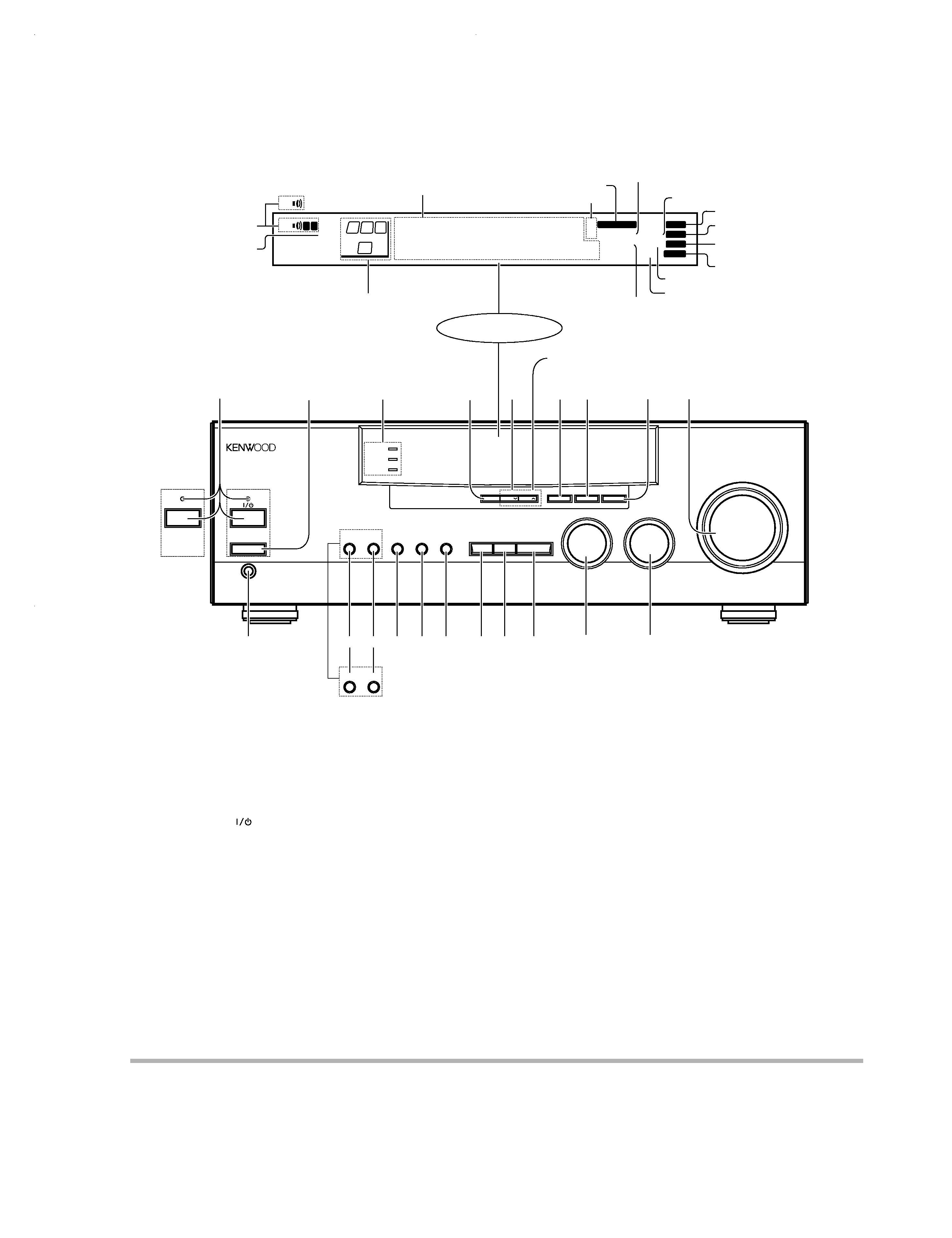
CONTROLS
8 FUNCTION SHIFT key
Use in combination with the numeric keys
to execute alternate commands.
9 Numeric keys
Provide functions identical to those of the
original remote control supplied with the
component you are controlling.
To access the functions printed above the
keys, press within 3 seconds of pressing
the FUNCTION SHIFT key. Function avail-
ability varies for each component.
0 SHIFT key
Use in combination with the AUDIO and
VIDEO keys to change the remote control
mode without changing the input selector
or in combination with the POWER key to
turn on and off components programmed
into the remote control.
! TV selector key
Sets the remote control to operate a TV or
cable box. This key does not change the
input selector on the receiver.
@ AUDIO selector key
Selects the audio inputs and sets the re-
mote control to operate the respective
KENWOOD audio component.
If you connect audio components from
KENWOOD and other makers to the MD/
TAPE or CD jacks, you can set the remote
control to operate these components by
registering the appropriate setup code at
the respective input.
# GUIDE key
Use to activate the OSD menu functions of
registered components.
$ VOLUME key
Use to adjust the receiver volume.
% MUTE key
Use to temporarily mute the sound.
^ SOUND key
Use to adjust the sound quality and ambi-
ence effects.
& LISTEN MODE key
Use to select the listening mode.
* SETUP key
Use to select the surround sound settings.
1 POWER key
Use to turn the receiver on and off.
Use in combination with the input selector
(AUDIO, VIDEO, or TV) keys and SHIFT
key to turn various components on and off.
2 MACRO key
Use in combination with the AUDIO, VIDEO,
or TV keys to execute a series of com-
mands automatically (MACRO PLAY).
3 VIDEO selector key
Selects the video inputs and sets the re-
mote control to operate the component
registered at the respective input.
4 Multi control keys
Use to operate the selected component.
5 REC key
Use to operate the selected component.
6 TUNING/SKIP key
Use during the setup procedure to specify
various settings. Use to operate the tuner
or selected component.
7 SUBWOOFER key
Use in combination with the VOLUME +/
keys to adjust the volume of the subwoofer.
There are some cases in which keys (or
knobs) that have the same function on
the receiver and on the remote control
have different names. In the instruc-
tions of this manual, if the names of
corresponding keys (or knobs) on the
receiver and remote control are differ-
ent, the name of the remote control key
is indicated in parentheses.
AUDIO
SHIFT
MACRO
TV
VIDEO
GUIDE
REC
MUTE
VOLUME
TUNING/SKIP
THEME
FAV
MENU
FUNCTION
SHIFT
SETUP
INFO
ALT AUD
TV/SAT/VID
REPEAT
RANDOM
+100
DISPLAY
ENT
+10
LISTEN
MODE
SOUND
SUBWOOFER
23
1
56
4
89
7
0
1
2
3
7
8
9
4
5
6
0
!
#
^
*
&
%
@
$
8
7
4¢
6
BAND
P. CALL
P. CALL
POWER
Remote control unit (RC-R0607, RC-R0507)
KRF-V5010(K)
COVER(
98.12.9
12:22
y[W
7