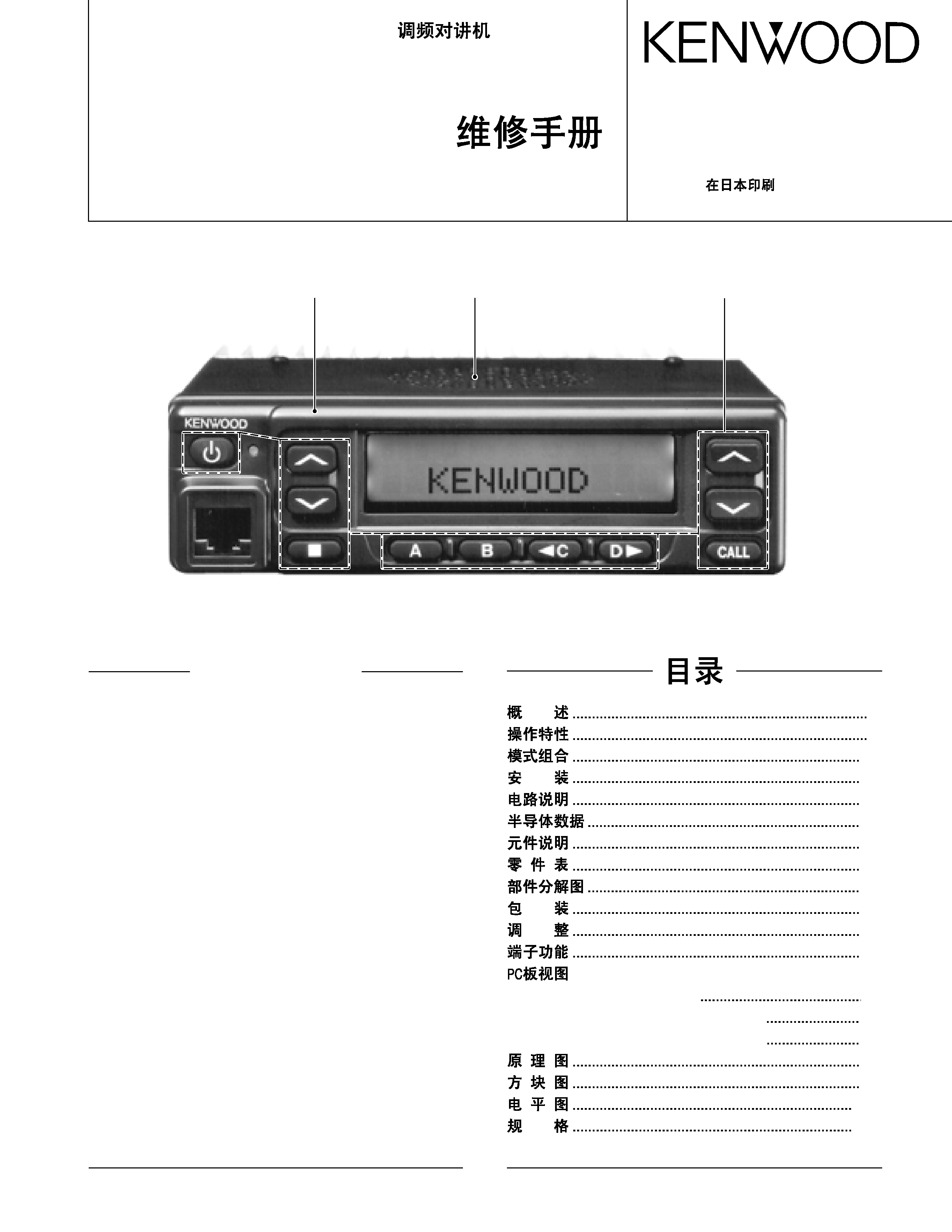
KENWOOD TK782 Service Manual

Cover page of KENWOOD TK782 Service Manual

Service Manual for KENWOOD TK782, downloadable as a PDF file.

Manual details

  • Immediate download after payment.
  • Delivered as a PDF file.
  • The manual has 90 pages
  • File size: 6.34 MB
  • Available language versions: Japanese, English
  • Different language versions may vary sligthly in file size and page count.

We guarantee that...

  • our manuals are complete,
  • the manual includes circuit diagrams,
  • our manuals are checked with antivirus,
  • We'll issue refund if the manual is damaged, incomplete or unreadable (our refund policy)

Sample pages

Thumbnail of page 1Thumbnail of page 2Thumbnail of page 3Thumbnail of page 4
Thumbnail of page 5Thumbnail of page 6Thumbnail of page 7Thumbnail of page 8
Thumbnail of page 9
background image
© 2002-3
B51-8619-00 (N) 611
TK-782
SERVICE MANUAL /
GENERAL ................................................................. 2
OPERATING FEATURES ......................................... 5
REALIGNMENT ...................................................... 23
INSTALLATION ...................................................... 28
CIRCUIT DESCRIPTION ......................................... 35
SEMICONDUCTOR DATA ..................................... 42
DESCRIPTION OF COMPONENTS ....................... 45
PARTS LIST............................................................ 49
EXPLODED VIEW .................................................. 57
PACKING ................................................................ 58
ADJUSTMENT ....................................................... 59
TERMINAL FUNCTION ......................................... 76
PC BOARD VIEWS
PLL/VCO (X58-4712-71) ................................... 78
TX-RX UNIT (X57-6143-01) (A/2)..................... 79
TX-RX UNIT (X57-6143-01) (B/2) ..................... 85
SCHEMATIC DIAGRAM ........................................ 89
BLOCK DIAGRAM .................................................. 97
LEVEL DIAGRAM................................................. 100
SPECIFICATIONS................................................. 102
CONTENTS
VHF FM TRANSCEIVER / VHF
Cabinet (Upper)
(A01-2165-23)
Panel assy
(A62-0642-03)
Key top
(K29-9105-22)
2
5
23
28
35
42
45
49
57
58
59
77
PLL/VCO (X58-4712-71)
78
TX-RX UNIT (X57-6143-01) (A/2)
79
TX-RX UNIT (X57-6143-01) (B/2)
85
89
97
100
103
background image
2
TK-782
GENERAL /
INTRODUCTION
SCOPE OF THIS MANUAL
This manual is intended for use by experienced techni-
cians familiar with similar types of commercial grade com-
munications equipment. It contains all required service in-
formation for the equipment and is current as of the publica-
tion data. Changes which may occur after publication are
covered by either Service Bulletins or Manual Revisions.
These are issued as required.
ORDERING REPLACEMENT PARTS
When ordering replacement parts or equipment informa-
tion, the full part identification number should be included.
This applies to all parts : components, kits, or chassis. If the
part number is not known, include the chassis or kit number
of which it is a part, and a sufficient description of the re-
quired component for proper identification.
PERSONNEL SAFETY
The following precautions are recommended for person-
nel safety :
! DO NOT transmit if someone is within two feet (0.6 meter)
of the antenna.
! DO NOT transmit until all RF connectors are verified se-
cure and any open connectors are properly terminated.
!
SHUT OFF and DO NOT operate this equipment near elec-
trical blasting caps or in an explosive atmosphere.
! All equipment should be properly grounded before power-
up for safe operation.
! This equipment should be serviced by a qualified techni-
cian only.
PRE-INSTALLATION CONSIDERNATIONS
1. UNPACKING
Unpack the radio from its shipping container and check
for accessory items. If any item is missing, please contact
KENWOOD immediately.
2. PRE-INSTALLATION CHECKOUT
2-1. Introduction
Each radio is adjusted and tested before shipment. How-
ever, it is recommended that receiver and transmitter opera-
tion be checked for proper operation before installation.
2-2. Testing
The radio should be tested complete with all cabling and
accessories as they will be connected in the final installa-
tion. Transmitter frequency, deviation, and power output
should be checked, as should receiver sensitivity, squelch
operation, and audio output. QT equipment operation should
be verified.
!
!
!
!
!
background image
3
TK-782
3. PLANNING THE INSTALLATION
3-1. General
Inspect the vehicle and determine how and where the ra-
dio antenna and accessories will be mounted.
Plan cable runs for protection against pinching or crush-
ing wiring, and radio installation to prevent overheating.
3-2. Antenna
The favored location for an antenna is in the center of a
large, flat conductive area, usually at the roof center. The
trunk lid is preferred, bond the trunk lid and vehicle chassis
using ground straps to ensure the lid is at chassis ground.
3-3. Radio
The universal mount bracket allows the radio to be
mounted in a variety of ways. Be sure the mounting surface
is adequate to support the radio's weight. Allow sufficient
space around the radio for air cooling. Position the radio
close enough to the vehicle operator to permit easy access
to the controls when driving.
3-4. DC Power and wiring
1. This radio may be installed in negative ground electrical
systems only. Reverse polarity will cause the cable fuse
to blow. Check the vehicle ground polarity before installa-
tion to prevent wasted time and effort.
2. Connect the positive power lead directly to the vehicle
battery positive terminal. Connecting the Positive lead to
any other positive voltage source in the vehicle is not rec-
ommended.
3. Connect the ground lead directly to the battery negative
terminal.
4. The cable provided with the radio is sufficient to handle
the maximum radio current demand. If the cable must be
extended, be sure the additional wire is sufficient for the
current to be carried and length of the added lead.
4. INSTALLATION PLANNING - CONTROL STATIONS
4-1. Antenna system
Control station. The antenna system selection depends
on many factors and is beyond the scope of this manual.
Your KENWOOD dealer can help you select an antenna sys-
tem that will best serve your particular needs.
4-2. Radio location
Select a convenient location for your control station radio
which is as close as practical to the antenna cable entry point.
Secondly, use your system's power supply (which supplies
the voltage and current required for your system). Make sure
sufficient air can flow around the radio and power supply to
allow adequate cooling.
GENERAL /
background image
4
TK-782
SERVICE
This radio is designed for easy servicing. Refer to the
schematic diagrams, printed circuit board views, and align-
ment procedures contained in this manual.
Note
When you modify your radio as described in system set-
up, take the following precaution.
The rating of pin 7 (SB) of the accessory connector cable
(KCT-19) on the rear of the radio is 13.6V (0.75A). Insert a 1A
fuse if you use the SB pin for external equipment.
Accessory connector
cable (KCT-19)
If you do not intend to use the 3.5-mm jack for the exter-
nal speaker, fit the supplied speaker-jack cap (B09-0235-05)
to stop dust and sand getting in.
1
3
+
7
6
13
15
Speaker-jack cap
(B09-0235-05)
1
3
+
7
6
13
15
GENERAL /
background image
5
TK-782
OPERATING FEATURES /
1. Operation Features
The TK-782 is a VHF FM radio designed in DTMF/DMS
model.
This transceiver can handle up to 250 groups with 250
channels in each group.
You can use option signalling which is DTMF or DMS (Digi-
tal Message System-FFSK signalling) for every channel.
2. Transceiver Controls and Indicators (Fig. 1)
2-1. Front Panel Controls
All the keys on the front panel are momentary-type push
buttons. The functions of these keys are explained below.
!
POWER key
Transceiver POWER key. When the power is switched
off, all the parameters, such as the group and channel, are
stored in memory. When the power is switched on again,
the transceiver returns to the previous conditions.
!
CHANNEL UP/DOWN key
!
CALL key (Programmable)
!"
key (Programmable)
!
A, B, C and D key (Programmable)
!
VOLUME UP/DOWN key (Programmable)
!
BUSY/TX LED
The BUSY indicator (Green LED) shows that the channel
is in use. The TX indicator (Red LED) shows that you are
transmitting.
2-2. Programmable Keys
The FPU (KPG-77D) enables programmable keys to select
the following functions.
"
Auto Dial
To transmit the stored DTMF code automatically. When
you select DTMF encode in the "Auto dial mode" menu, Auto
dial, Redial, Dial ID and Store
Send modes are available.
Press the [Auto dial] key to enter the "Auto dial mode".
Select the desired number to send. It is use the [Channel
up] and [Channel down] keys, or the [2] and [8] keys on the
microphone to select. Press the [*] key to transmit the num-
bers.
!
!
!
!
!
!
!
"

Reviews

There are no reviews of this manual yet.