KRF-V4530D/V5030D/V6030D/VR-405/406/414
3
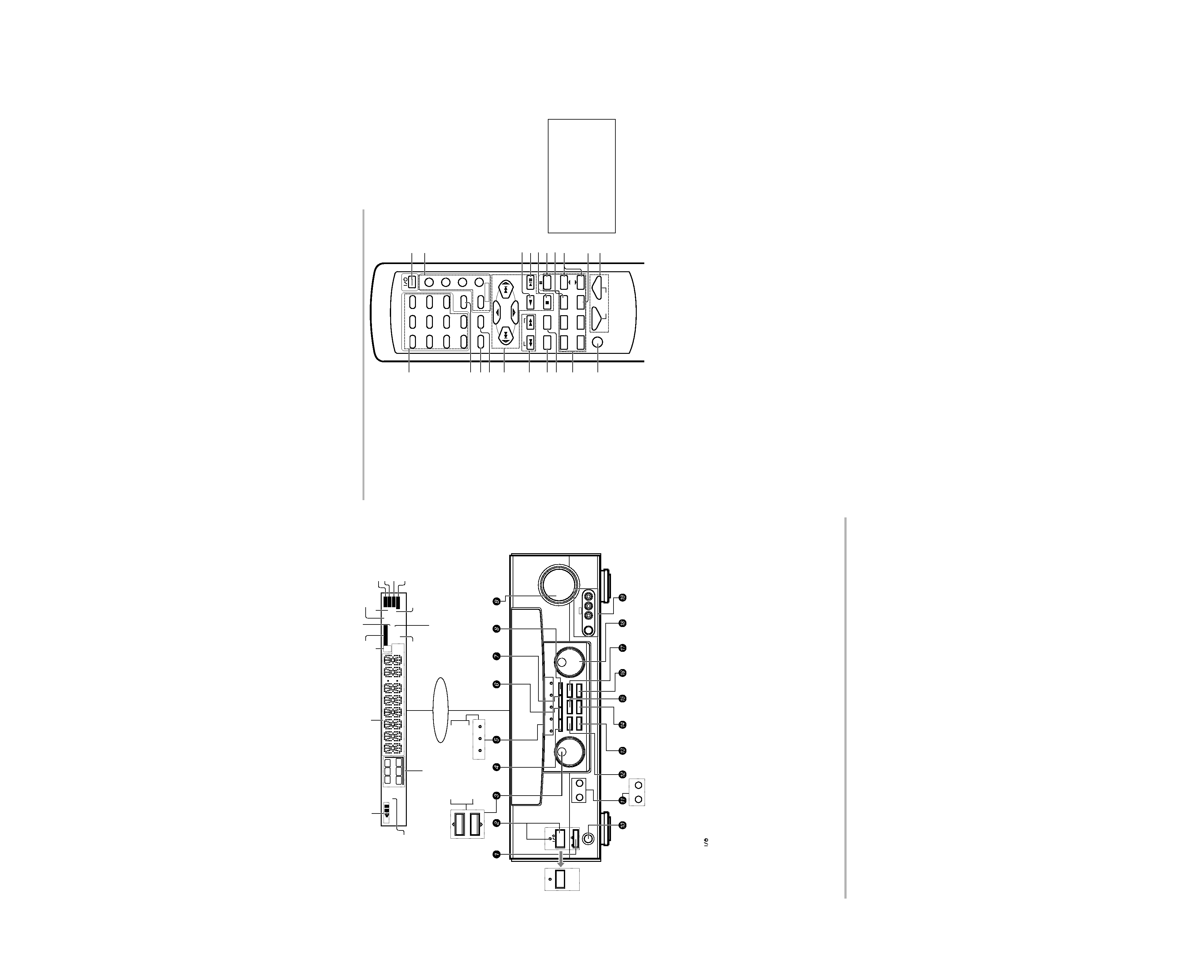
CONTROLS
7 B. BOOST key
Use to select the maximum adjustment
setting for the low frequency range.
RECEIVER key
Use to return to the operation of the re-
ceiver.
8 DISC SKIP key
If CD is selected as the input source, this key
functions as the multi-CD player disc skip
key.
A/B key
If TAPE is selected as the input source, this
(A and B) of a double cassette deck.
+100 key
Use to select the disc number with the
multi-CD player.
TITLE key
Use to operate other components.
9 INPUT SELECTOR keys (DVD, PHONO,
CD/DVD, TUNER, MD/TAPE, VIDEO1,
VIDEO2, VIDEO3, AV AUX)
Selects the inputs and sets the remote
control to operate the component regis-
tered at the respective input.
0 MUTE key
Use to temporarily mute the sound.
! POWER key
Use to turn the receiver on and off.
@ POWER key (TV, VCR, DVD, DSS/CDR,
CABLE)
Use to turn the other components on and
off.
# ENTER key
Use to operate other components.
2 key
If tape is selected as the input source, this
key functions as the play key for side B of
the cassette (the side facing away from the
front of the deck).
$ BAND key
Use to select the broadcast band.
6 key
If CD is selected as the input source, this
key functions as the play/pause key.
If MD is selected as the input source, this
key functions as the play key.
% AUTO key
Use to select the auto tuning mode.
7 key
If CD or MD is selected as the input source,
this key functions as the stop key.
^ 8 key
Use to operate other components.
& INPUT SEL. key
Use to operate other components.
* CHANNEL %/fi keys
Use to select the channel.
( TV SEL. key
Use to operate other components.
) VOLUME keys
Use to adjust the receiver volume.
1 Numeric keys
Provide functions identical to those of the
original remote control supplied with the
component you are controlling.
2 LSTN.M key
Use to select the listening mode.
RETURN key
Use to operate other components.
3 SET UP key
Use to select the surround sound settings.
MENU key
Use to operate other components.
4 SOUND key
Use to adjust the sound quality and ambi-
ence effects.
OSD key
Use to operate other components.
5 MULTI CONTROL keys
Used to make a variety of settings.
Use to operate other components.
P.CALL
@/# keys
If tuner is selected as the input source,
these keys function as P.CALL keys.
4/¢ keys
If CD or MD is selected as the input source,
these keys function as search keys.
6 TUNING 1/¡ keys
Use to operate the tuner or selected com-
ponent.
There are some cases in which keys (or
knobs) that have the same function on the
receiver and on the remote control have
different names. In the instructions of this
manual, if the names of corresponding
keys (or knobs) on the receiver and remote
control are different, the name of the re-
mote control key is indicated in parenthe-
ses.
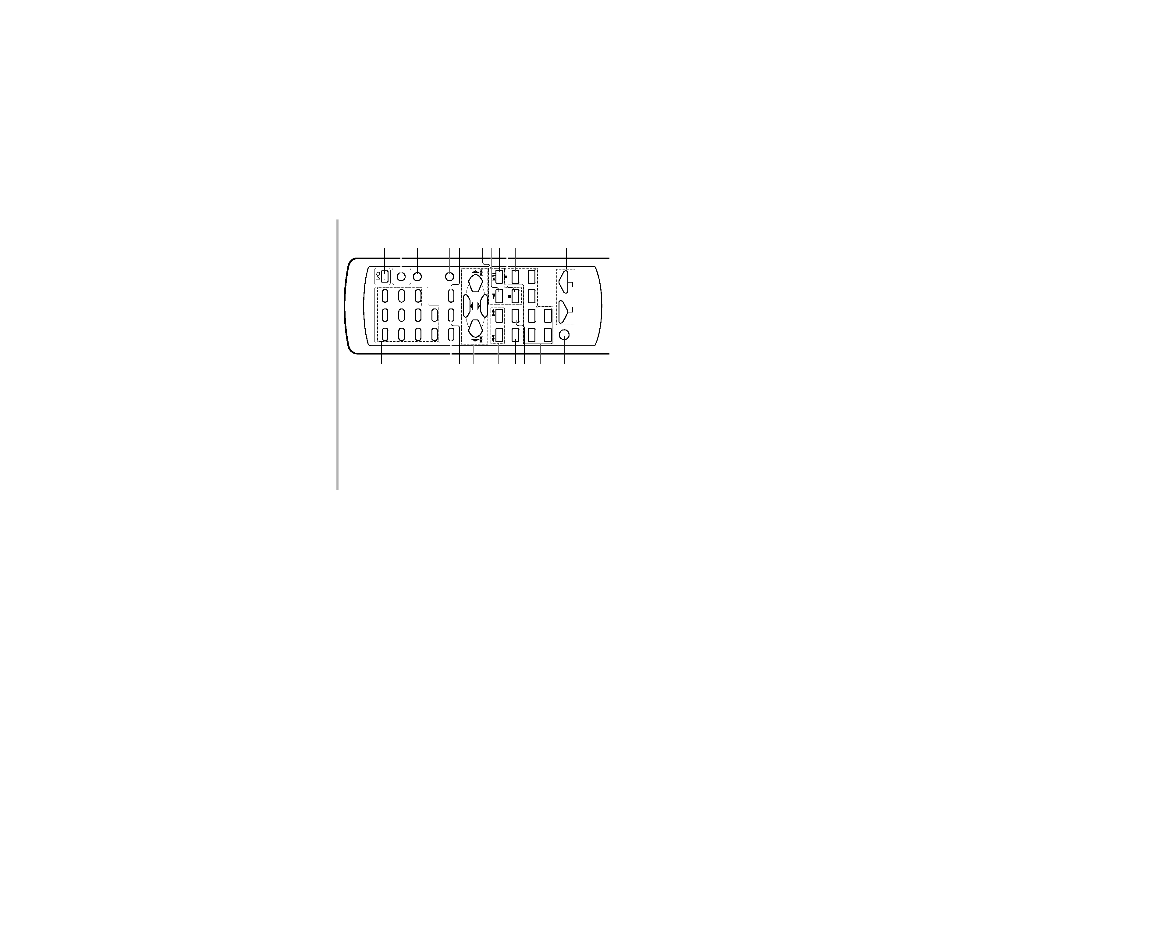
Remote control unit (RC-R0609) (VR-407/406/KRF-V7030D/V6030D)
1
B.BOOST
DISC SKIP
DVD
PHONO
CD/DVD
TUNER
MD/TAPE
VIDEO1
VIDEO2
VIDEO3
AV AUX
23
POWER
POWER
TV
VCR
DVD
CABLE
DSS/CDR
RETURN
OSD
MENU
P.CALL
TUNING
MUTE
VOLUME
A/B+100
TITLE
RECEIVER
AUTO
INPUT SEL.
TV SEL.
CHANNEL
ENTER
BAND
P.CALL
MULTI CONTROL
45
6
78
9
0
+10
LSTN.M
SET UP
SOUND
1
7
9
8
0
2
4
3
5
6
!
@
^
*
)
$
#
%
&
(
CDR
CD
CLIP
DSP
TI.VOL
TP
RDS
EON
PTY
TA
NEWS
FM
AM
MHz
kHz
PRO LOGIC
3 STEREO
DOWN MIX
DIGITAL
S.DIRECT
MONITOR
MEMO
ST.
TUNED
AUTO SOUND
AUTO
SP
LFE
SW
C
AB
MUTE
S
RS
LS
R
L
A SPEAKERS B
STANDBY
POWER
MULTI CONTROL
MULTI CONTROL
LISTEN MODE
SOUND
SOURCE DIRECT
AUTO
BAND
MEMORY
INPUT SELECTOR
VOLUME CONTROL
UP
DOWN
PROLOGIC
3 STEREO
DOWN MIX
DOLBY
DIGITAL
DTS
INPUT MODE
SET UP
S-VIDEO
V
L AUDIO R
AV AUX
DIMMER
MONITOR
PHONES
ON/STANDBY
ON
OFF
STANDBY
POWER
ON/STANDBY
PROLOGIC
3 STEREO
DOLBY
DIGITAL
SPEAKER
MUTE
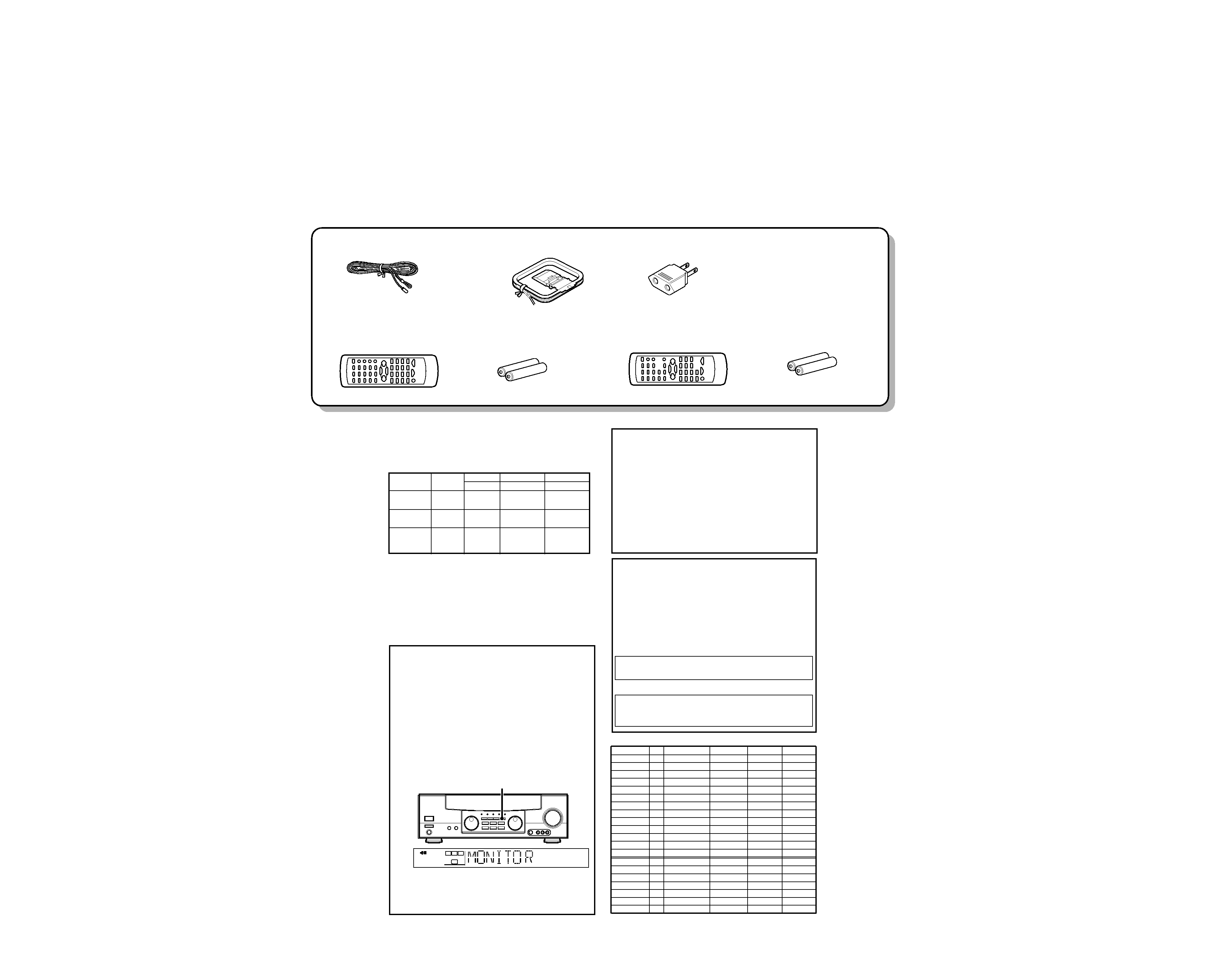
Display
Speaker selection indicators
Input channel indicators
Output channel indicators
Band indicators
AUTO indicator
MEMO. indicator
ST. indicator
TUNED indicator
3 STEREO indicator
STEREO indicator
Frequency display,
Input display,
Preset channel display,
Surround mode display
Speaker indicator
PRO LOGIC
indicator
S.DIRECT indicator
MONITOR indicator
DOWN MIX indicator
For U.S.A.
and Canada
MUTE indicator
AUTO SOUND indicator
DIGITAL indicator
For VR-407, KRF-V7030D
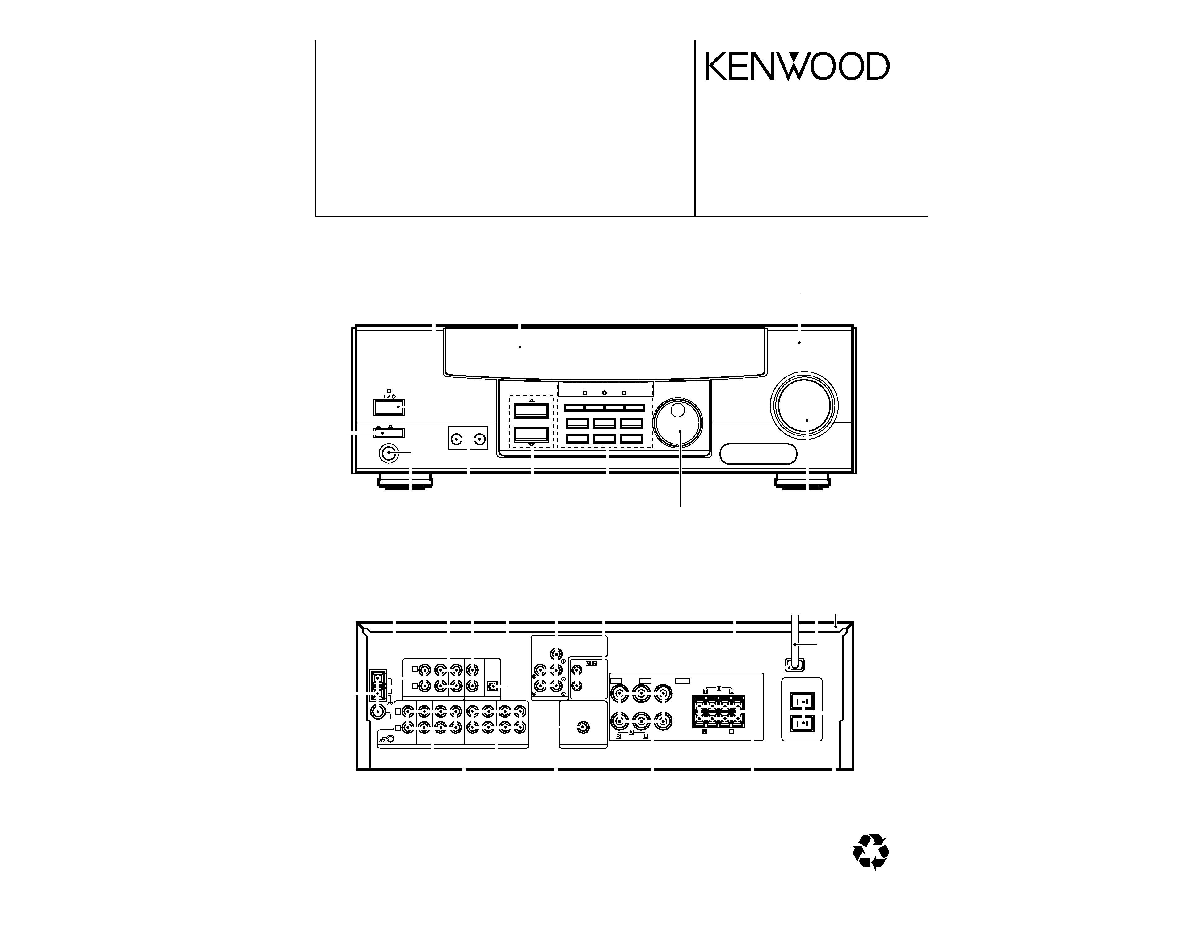
1 POWER key
(Except for U.S.A. and Canada)
Use to turn the main power ON/OFF.
2 POWER key
(For U.S.A. and Canada)
Use to turn the power ON/OFF.
STANDBY indicator
2 ON/STANDBY (
) key
(Except for U.S.A. and Canada)
Use to switch the power ON/STANDBY when
the POWER is turned ON.
STANDBY indicator
3 MULTI CONTROL knob
(For VR-407/KRF-V7030D)
Used to make a variety of settings.
3 MULTI CONTROL keys
(For VR-406/405/414/KRF-V6030D/V5030D/
V4530D)
Used to make a variety of settings.
4 SET UP key
Use to select the surround sound settings.
5 Surround indicators
÷ DTS indicator
(For VR-407/KRF-V7030D)
Lights when the receiver is in the DTS mode.
÷ DOLBY DIGITAL indicator
Lights when the receiver is in the Dolby
Digital mode.
÷ PROLOGIC indicator
Lights when the receiver is in the
PROLOGIC mode.
÷ 3 STEREO indicator
Lights when the receiver is in the 3 STE-
REO mode.
÷ DOWN MIX indicator
(For VR-407/KRF-V7030D)
Lights when the receiver is in the DOWN
MIX mode.
6 INPUT MODE key
Use to switch between the digital and analog
inputs.
7 DIMMER key
Use to adjust the brightness of the display.
Use to select the REC MODE.
8 MONITOR key
Use to monitor the source that is connected to
the MONITOR jack.
9 VOLUME CONTROL knob
0 PHONES jack
Use for headphone listening.
! SPEAKERS A/B keys
(For VR-407/406/KRF-V7030D/V6030D)
Use to turn the A/B speakers ON/OFF.
! SPEAKER key
(For VR-405/414/KRF-V5030D/V4530D)
Use to turn the speaker ON/OFF.
MUTE key
(For VR-405/414/KRF-V5030D/V4530D)
Use to temporarily mute the sound.
@ SOUND key
Use to adjust the sound quality and ambience
effects.
# BAND key
Use to select the broadcast band.
$ AUTO key
Use to select the auto tuning mode.
% LISTEN MODE key
Use to select the listening mode.
^ MEMORY key
Use to store radio stations in the preset
memory.
& SOURCE DIRECT key
Use to pass the source material direct to the
amplifier.
* INPUT SELECTOR knob
Use to select the input sources.
( AUX IN S VIDEO/VIDEO/AUDIO L/R
jacks
(For VR-407/KRF-V7030D)
Standby mode
While the standby indicator of the unit is lit, a small amount of current is flowing into the unit's internal circuitry to back up the memory. This condition is referred
to as the standby mode of the unit. While the unit is in the standby mode, it can be turned ON from the remote control unit.
For VR-405, VR-414,
KRF-V5030D,
KRF-V4530D
For VR-406, VR-405, VR-414
KRF-V6030D, KRF-V5030D,
KRF-V4530D