KENWOOD R-SE9 Service Manual

Cover page of KENWOOD R-SE9 Service Manual

Service Manual for KENWOOD R-SE9, downloadable as a PDF file.

Manual details

  • Immediate download after payment.
  • Delivered as a PDF file.
  • The manual has 23 pages
  • File size: 2.93 MB
  • Available language versions: English
  • Different language versions may vary sligthly in file size and page count.

We guarantee that...

  • our manuals are complete,
  • the manual includes circuit diagrams,
  • our manuals are checked with antivirus,
  • We'll issue refund if the manual is damaged, incomplete or unreadable (our refund policy)

Sample pages

Thumbnail of page 1Thumbnail of page 2Thumbnail of page 3Thumbnail of page 4
Thumbnail of page 5Thumbnail of page 6Thumbnail of page 7Thumbnail of page 8
Thumbnail of page 9
background image
PRECAUTIONS FOR REPAIR
· For the SERIAL TEST CODE LIST of the circuit description, see Service manual (B51-5210-00) of R-SA7.
· For the INITIAL STATE, the BACK UP and the MICROPROCESSOR of the circuit description, see Service manual (B51-
5373-00) of R-SE7.
· No connection of ground line if disassemble the unit.
· Please connection the ground line on rear panel, PCBs, Chassis and some others.
STEREO INTEGRATED AMPLIFIER/TUNER
R-SE9
SERVICE MANUAL
©1997-10/B51-5375-00 (K/K) 888
band
volume control
auto/mono
enter
phones
mode
pure
multi control
N.B.
down
up
stereo integrated amplifier/tuner
R-SE9
A
TRAITR
on/standby
SYSTEM
CONTROL
ANTENNA
AM
GND
FM75
CD
IN
IN
REC
PLAY
SUPER
WOOFER
PRE OUT
SPEAKERS
( 6 - 16
)
L
R
TAPE
REC
PLAY
MD
AUX
R
L
Side plate
(A50-1303-02)
Panel*
(A60-)
Front glass
(B10-2369-03)
AC power cord *
(E30-)
Screw terminal board
(E70-0061-05)
Lock terminal board
(E20-0476-05)
Phono jack
(E63-1014-05)
Phono jack
(E63-0046-15)
Phono jack
(E63-0047-15)
Rectangular receptacle
(E08-0312-05)
Metallic cabinet
(A01-3463-11)
Power cord bushing
(J42-0083-05)
Knob
(K29-6741-04)
Knob
(K29-6738-04)
Knob
(K29-6739-04)
Knob
(K29-6751-04)
(HM-901)
* Refer to parts list on page 21.
R-SE9(K) 1P 97.11.29 3:34 AM y[W 2
background image
FM indoor antenna (1)
(T90-0182-15) : M
(T90-0806-05) : T
DISPLAY
SLEEP
TAPE
REMOTE
CONTROL
UNIT
RC-SE9
1
2
3
RANDOM
4
5
6
CLEAR
7
8
9
P.MODE
O.T.E.
0
+10
EDIT
TUNER BAND
INPUT
N.B.
MUTE
VOLUME CONTROL
MD
CD
P.CALL
Batteries (R6/AA) (2)
AM loop antenna stand (1)
(J19-3645-05)
AM loop antenna (1)
(T90-0820-05)
Audio cords (2)
(E30-0615-05)
System control cord (1)
(E30-2628-05)
Battery cover (A09-0374-08)
Remote control unit (1)
(A70-1154-05) : M .................RC-SE9
(A70-1155-05) : T ..................RC-SE9(E)
R-SE9
CONTENTS / ACCESSORIES
2
CONTENTS / ACCESSORIES .................................. 2
CIRCUIT DESCRIPTION ............................................3
ADJUSTMENT ............................................................5
PC BOARD ................................................................ 6
SCHEMATIC DIAGRAM ............................................ 9
EXPLODED VIEW ....................................................20
PARTS LIST..............................................................21
SPECIFICATIONS ....................................................27
Contents
Accessories
System configuration
SYSTEM NAME
AMP/TUNER
CD PLAYER
SPEAKER
HM-901
R-SE9
DP-SE9
LS-SE9
R-SE9(K) 1P 97.11.29 3:34 AM y[W 3
background image
R-SE9
3
CIRCUIT DESCRIPTION
1. DESTINATION LIST OF TUNER
1-1 Destination List of Tuner
2. TEST MODE
2-1. Initializing
The system is initialized when the power is turned on while
pressing the POWER key.
(1) Contents of operation
E
All the functions are initialized.
2-2. AMP test mode using main unit's keys
2-2-1. Entering the AMP test mode
E
Turn on the power while pressing the BAND key.
2-2-2. Canceling the AMP test mode
E
By turning off the power, the system is initialized and the
test mode is canceled.
2-2-3. Contents of AMP test mode
(1) Automatic POWER ON
E
The POWER ON state is entered whenever the power is
turned on while pressing the BAND key. All functions are
then initialized and activated in the all-lighting mode.
E
Sub-clock oscillation diagnosis function
The oscillation diagnosis (existence of oscillation and
measurement of period) of a sub-clock is performed
before the test mode is entered. If the diagnosis result is
OK, the system enters the test mode.
If the diagnosis result is NG, the oscillation of the sub-
clock is diagnosed again. If the result is OK, the system
enters the test mode. If the diagnosis result is continu-
ously NG five times, the system stops with ERR 1 and
ERR 2 displayed.
(2) All-lighting mode
E
All the fluorescent display indicators and LED lamps light
when the power is turned on while pressing the BAND
key.
E
After that, the all-lighting mode is canceled when any
main unit's key is pressed. The normal display obtained
when the selector is set to TUNER then appears.
(4) Others
E
The AMP test mode is not terminated even if the selector
is set to positions other than TUNER.
E
In the AMP test mode, the muting during mode selection
is not controlled. However, the operation during the
power-on sequence is the same as the normal operation.
E
The SP protection operation is also the same as the nor-
mal operation.
E
In the AMP test mode using main unit's keys, the keys
below provide a special operation according to the posi-
tion where the selector is set. The main unit's keys
except described below and the rotary encoder provide
the normal operation.
(5) When selector is set to TUNER
Key
Operation
PURE A key
Increments the P.CALL every time this
key is pressed.
N.B. key
Decrement the P.CALL every time this
key is pressed.
ENTER key
Selects the display cyclically in the order
below every time this key is pressed.
@
Write data in the unused area of E2PROM, then read the
written data. If the read data is the same as the written
data, "RAM OK" is displayed in the fluorescent display
indicator. If the former is different from the latter, "RAM
NG" is displayed.
A
Set the TUNER ATT to OFF and display the S level in
hexadecimal when the ENTER key is pressed. ("ATT
OFF **" is displayed in the fluorescent display indicator.)
B
Set the TUNER ATT to ON and display the S level in
hexadecimal when the ENTER key is pressed. ("ATT ON
**" is displayed in the fluorescent display indicator.)
* The special display using the ENTER key is continued until
the next operation is carried out. (**: S LEVEL)
When keys other than ENTER are pressed in items
@
to
B
above, the TUNER ATT is set to OFF and the normal display
appears. The operation corresponding to the key that has
been pressed is performed in this case.
Desti-
Receive
Channel
PLL
DIODE SW(X14)
nation
BAND frequency
space
1F
reference DSW1 DSW2
range
frequency
D26
D29
FM
87.5MHz~
100kHz +10.7MHz
25kHz
K1
108.0MHz
AM
530kHz~
10kHz
+450kHz
10kHz
1
1
1700kHz
FM
87.5MHz~
50kHz
+10.7MHz
25kHz
E1
108.0MHz
AM
531kHz~
9kHz
+450kHz
9kHz
0
1
1602kHz
FM
87.5MHz~
50kHz
+10.7MHz
25kHz
E3
108.0MHz
(RDS)
AM
531kHz~
9kHz
+450kHz
9kHz
1
0
1602kHz
M
K2 or E1 is changed the setting "DSW1".
X
1
(DSW1=1 : K2, 0 = E1)
0 : NO DIODE
1 : DIODE
X : SWITCHING TRANSISTOR
3) CONSTRAINT IDLING CURRENT CHANGEOVER MODE
when selector is set to positions other than TUNER.
[PURE A key] Every time this key is pressed.
idling current mode is selected cyclically.
î NORMAL(B class)îPURE A(IDLING MID)îPURE A(IDLING HIGH)ì
PURE A NORMAL (MIDíîHIGH AUTO CHANGEOVER)
IDLING CURRENT MODE
DISPLAY
PURE A IDLING MID (constraint)
PURE A M
PURE A IDLING HIGH (constraint)
PURE A H
PURE A NORMAL MID (less than VOL.10.00)
PURE A T M
PURE A NORMAL HIGH (more than VOL.10.01)
PURE A T H
R-SE9(K) 1P 97.11.29 3:34 AM y[W 6
background image
R-SE9
4
CIRCUIT DESCRIPTION
[ AUTO key ] Selects the MUTE operation and equalizer
cyclically in the order below for operation display every time
this key is pressed.
-- -> MUTE operation -> Minimum -> Maximum -> Pre-condition --
In the operation for except the AUTO key, become pre-
condition equlizer .
Pre condition : The equlizer becomes the condition to be
pushed the AUTO key before
(include N.B. circuit).
(7) SERIAL TEST CODE LIST
Refer to Service manual (B51-5210-00) of R-SA7 on
page 7.
[ BAND key ] Every time this key is pressed, all the displays
go off and the normal display is selected cyclically.
2-3. RDS test mode using main unit's keys
2-3-1. Entering the RDS test mode
E
Turn on the power while pressing the TUNING UP key.
2-3-2. Canceling the RDS test mode
E
By turning off the power, the system is initialized and the
test mode is canceled.
2-3-3. Contents of RDS test mode
E
The POWER ON state is entered whenever the power is
turned on while pressing the TUNING UP key. All the
functions are then initialized.
E
In the RDS test mode using main unit's keys, the keys
below provides a special operation according to the posi-
tion where the selector is set. The main unit's keys
except described below and the rotary encoder provide
the normal operation.
Key
Operation
CLASS A key
Performs the same operation as for
remote control key "DISPLAY" every time
this key is pressed.
INPUT SEL. key
Performs the same operation as for
remote control key "PTY" every time this
key is pressed.
N.B. key
Performs the same operation as for
remote control key "TA" every time this
key is pressed.
ENTER key
Selects the display cyclically in the order
below every time this key is pressed.
@
Write data in the unused area of EEPROM, then read the
written data. If the read data is the same as the written
data, "RAM OK" is displayed in the fluorescent display
indicator. If the former is different from the latter, "RAM
NG" is displayed.
A
Set the TUNER ATT to OFF and display the S level in
hexadecimal when the ENTER key is pressed. ("ATT
OFF **" is displayed in the fluorescent display indicator.)
B
Set the TUNER ATT to ON and display the S level in
hexadecimal when the ENTER key is pressed. ("ATT ON
**" is displayed in the fluorescent display indicator.)
* The special display using the ENTER key is continued until
the next operation is carried out. (**: S LEVEL)
When keys other than ENTER are pressed in items
@
to
B
above, the TUNER ATT is set to OFF and the normal display
appears. The operation corresponding to the key that has
been pressed is performed in this case.
2-4. SERIAL TEST MODE
(1) Setting the serial test mode
The unit is put into the serial test mode when a serial code
"TEST ON" is input during the POWER-ON sequence.
In the 16-bit serial test mode, serial code C27FH is input.
E
In the serial test mode, all remote control keys and ordi-
nary serial codes are disabled. Only the panel keys per-
form the same operation as usually.
(2) Canceling the serial test mode
E
The serial test mode is canceled to return to the ordinary
mode by inputting a "TEST OFF" code (C27 EH). After
the ordinary mode was returned, the serial mode is
returned to the state before the test mode is entered.
The backup operation is not initialized.
E
The serial test mode is also canceled when the AC power
is turned OFF.
(3) Cautions
E
The serial test code is prescribed as a 16-bit code only.
E
The operations below are inhibited in the serial test mode.
The operations mentioned above cannot be guaranteed
when they are performed in the serial test mode.
E
An identical code is output when the serial test mode
code is input.
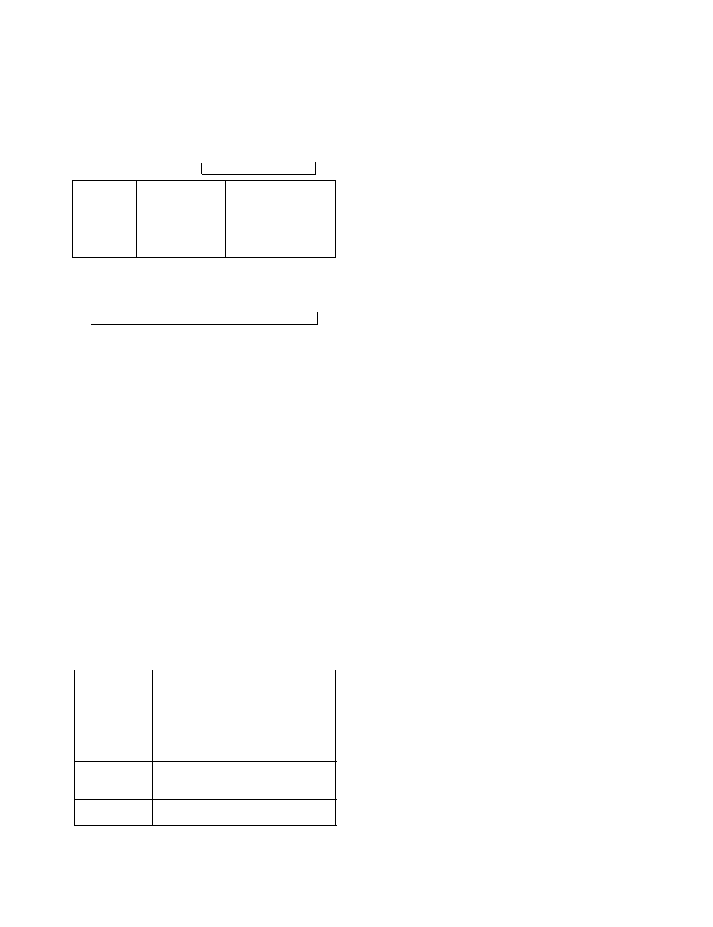
(6) When selector is set to positions other than TUNER
[ENTER key] Every time this key is pressed, master VOL-
UME level is selected cyclically.
INITIALIZE level ìî MAX î MID î MIN ì
Value of Master
VOLUME
Press the ENTER key.
Press the PURE A key,
then press the ENTER key.
MAX
86
16.00
MID
40
8.00
MIN
1
0.20
INITIALIZE
7
1.40
R-SE9(K) 1P 97.11.29 3:34 AM y[W 7
background image
R-SE9
5
ADJUSTMENT
NO.
ITEM
INPUT
SETTINGS
OUTPUT
SETTINGS
TUNER
SETTINGS
ALIGNMENT
POINTS
ALIGN FOR
FIG.
1
DISCRIMINATOR
(A)
98.0kHz
1kHz, ±75kHz dev.
60dBµ(ANT input)
Connect a DC
voltmeter
between
Pin 1 and Pin 2
of CN 2.
MONO
98.0MHz
L 31
0V
(a)
L 32
Minimum distortion.
2
DISTORTION
(STEREO)
(C)
98.0MHZ
1kHz, ±68.25kHz dev.
Pilot: ±6.75kHz dev.
60dBµ(ANT input)
(B)
AUTO
98.0MHz
IFT (A1)
Minimum distortion.
(a)
NO.
ITEM
INPUT
SETTINGS
OUTPUT
SETTINGS
AMP SETTINGS
ALIGNMEN
T POINTS
ALIGN FOR
FIG.
POWER: ON
1
A CLASS
B CLASS
IDLE CURRENT
--
Connect a DC
voltmeter
across
CN9(L)
CN10(R)
(X09, A/4)
PURE A : ON
PURE A : OFF
Volume : 0
VR1(L)
VR2(R)
(X09, A/4)
18mV
(b)
2
A CLASS
IDLE CURRENT
--
[EXCEPT TUNER]
PURE A : ON
Volume : 0.20~10.00
Less than 90mV.
(Check)
3
A CLASS
IDLE CURRENT
--
[EXCEPT TUNER]
PURE A : ON
Volume : 10.20~16.00
Less than 250mV.
(Check)
SYSTEM
CONTROL
ANTENNA
AM
GND
FM75
CD
IN
IN
REC
PLAY
SUPER
WOOFER
PRE OUT
SPEAKERS
( 6 - 16
)
L
R
TAPE
REC
PLAY
MD
AUX
R
L
Oscilloscope
Distortion meter
AC voltmeter
Dummy antenna
(A)
(B)
(C)
(D)
AG
AG
FM SG
MPX
AG
FM SG
AM SG
(a)
(b)
CN9(L)
CN10(R)
Dc voltmeter
18mV
FM SECTION
X05-4622-71 (T TYPE)
AUDIO SECTION (X09-470x-xx)
SYSTEM CONNECTIONS
R-SE9(K) 1P 97.11.29 3:34 AM y[W 10

Reviews

There are no reviews of this manual yet.