KENWOOD KTF2010 Service Manual

Cover page of KENWOOD KTF2010 Service Manual

Service Manual for KENWOOD KTF2010, downloadable as a PDF file.

We also have owner's manual to this model.

Manual details

  • Immediate download after payment.
  • Delivered as a PDF file.
  • The manual has 20 pages
  • File size: 1.48 MB
  • Available language versions: English
  • Different language versions may vary sligthly in file size and page count.

We guarantee that...

  • our manuals are complete,
  • the manual includes circuit diagrams,
  • our manuals are checked with antivirus,
  • We'll issue refund if the manual is damaged, incomplete or unreadable (our refund policy)

Sample pages

Thumbnail of page 1Thumbnail of page 2Thumbnail of page 3Thumbnail of page 4
Thumbnail of page 5Thumbnail of page 6Thumbnail of page 7Thumbnail of page 8
Thumbnail of page 9
background image
AM-FM STEREO SYNTHESIZER TUNER
KTF-2010/3010
SERVICE MANUAL
© 1998-1/B51-5407-00 (K/K) 2106
How to reset the microcomputer
The microcomputer may malfunction (impossibility operation,erro-
neous display,etc.)when the power cord is unplugged and plugged
in again while the unit is in ON mode with the Key pressed or due
to other extern al causes.In this case,execute the procedure on the
right to reset the microcomputer and return the unit to the normal
condition
Unplug the power cord form the wall outlet.
While pressing and holding the (ON/STANDBY) key,
plug the AC cord into the wall outlet again
·Resetting the microcomputer clears the memory you entered and
returns in to the initial condition when the unit left the factory.
HIGH
BLEND
WIDE
NARROW
RF
ATT
AUTO/MANUAL
+ 10/CLEAR
1
ACTIVE
RECEPTION
IF BAND
TA/NEWS
PTY/
PTY SEARCH
RF ATT
DISPLAY
ANT A/B
MEMORY
AM-FM STEREO SYNTHESIZER TUNER KTF-2010
BAND
P. CALL
DOWN
UP
TUNING/MULTI CONTROL
3
4
5
6
7
8
9
0/CHARA
2
ON/STANDBY
ANTENNA
GND
AM
FM 75
SYSTEM
CONTROL
OUTPUT
R
L
SL16 XS 8
KENWOOD badge
(B43-0302-04)
Knob
(K29-6882-03)
Panel
(A60-1336-02)
Metallic cabinet
(A01-3559-01)
Power cord bushing
(J42-0083-05)
Slide switch
(S31-2132-05)
Miniature phone jack
(E11-0188-05)
AC power code*
(E30-)
Lock terminal board
(E20-0321-05)
Phono jack
(E63-0068-15)
Front glass *
(B10-)
Knob
(K29-6883-04)
Illustration is KTF-2010.
* Refer to parts list on page 18.
(K)KTF-20101P( 98.4.254:21PM y[W 2
background image
TUNED
AUTO
kHz
MHz
STEREO
STANDBY
ANT A
B
MEMO
TA NEWS
TP
PTY
AR
RDS
EON
*
* * *
* * * *
.
MW
LW
FM
HIGH
BLEND
WIDE
NARROW
RF
ATT
TUNING MODE
+ 10/CLEAR
1
ACTIVE
RECEPTION
IF BAND
TA/NEWS
PTY/PTY
SEARCH
RF ATT
DISPLAY
ANT A/B
MEMORY
AM-FM STEREO SYNTHESIZER TUNER KTF-3010
BAND
P. CALL
DOWN
UP
TUNING/MULTI CONTROL
3
4
5
6
7
8
9
0/CHARA
2
ON/STANDBY
STANDBY indicator
RDS indicator
AR indicator
TA indicator
TP indicator
MEMORY indicator
PTY indicator
Antenna A/B indicator
Kilohertz indicator
Frequency display
Preset channel display
STATION NAME display
Magahertz indicator
Receiving band indicator
Signal indicator
EON indicator
Tuning mode indicator
TUNED indicator
Reception mode indicator
NEWS indicator
1
2
0
9
&
3 4 5 6 7 8
*
@
!
% ^
# $
Display
AUTO/MANUAL with the KTF-2010
· Lead wire antenna...................1
(T90-0809-05)
· Audio cord ...............................1
(E30-0505-05)
· AM loop antenna ass'y ........1
(T90-0195-05)
· System control cord ................1
(E30-2733-05)
· Loop antenna stand
(J19-3645-05)
· AC plug adapter ......................1
(E03-0115-05)
(M type only)
KTF-2010/3010
2
ACCESSORIES / CONTROLS
Accessories
Controls
1
1 POWER key
Press to turn on/off the power.
2
2 ACTIVE RECEPTION key(KTF-
3010 only)
Press to obtain the optimum reception con-
ditions for the signals being received.
3
3 IF BAND key(KTF-3010 only)
Press to the intermediate frequency pass
band between WIDE(wide band) and NAR-
ROW(narrow band).
4
4 RF ATT(KTF-3010 only)
Press to minimize the RF reciprocal modula-
tion and mixed modulation distortion when
there is an adjacent channel with strong.
5
5 ATT A/B key(KTF-3010 only)
Press to select the antenna when using 2
antennas.
6
6 HIGH BLEND indicator(KTF-3010
only)
7
7 WIDE indicator(KTF-3010 only)
8
8 NARROW indicator(KTF-3010
only)
9
9 RF-ATT indicator (KTF-3010 only)
0
0 AUTO/MANUAL key(KTF-2010)
TUNING MODE key(KTF-3010)
Press to select the tuning mode.
!
! BAND key
Press to switch the broadcast band.
@
@ TUNING/MULTI CONTROL knob
Used for tuning broadcast stations, selecting
the program type and entering characters.
#
# TA/NEWS key
$
$ PTY/PTY SEARCH key
%
% DISPLAY key
^
^ MEMORY key
Used for storing broadcast stations and
entering station names.
&
& Numeric keys
Used for storing and calling up broadcast
stations and entering station names.
*
* P.CALL key
Press to recall a preset station.
(K)KTF-20101P( 98.4.254:21PM y[W 3
background image
KTF-2010/3010
3
EXTERNAL VIEW
Illustration is KTF-3010.
HIGH
BLEND
WIDE
NARROW
RF
ATT
TUNING MODE
+ 10/CLEAR
1
ACTIVE
RECEPTION
IF BAND
TA/NEWS
PTY/
PTY SEARCH
RF ATT
DISPLAY
ANT A/B
MEMORY
AM-FM STEREO SYNTHESIZER TUNER KTF-3010
BAND
P. CALL
DOWN
UP
TUNING/MULTI CONTROL
3
4
5
6
7
8
9
0/CHARA
2
ON/STANDBY
ANTENNA
GND
AM
FM
75
B
A
SYSTEM
CONTROL
OUTPUT
R
L
SL16 XS 8
KENWOOD badge
(B43-0302-04)
Knob
(K29-6928-03)
Panel
(A60-1357-02)
Metallic cabinet
(A01-3559-01)
Power cord bushing
(J42-0083-05)
Slide switch
(S31-2132-05)
Miniature phone jack
(E11-0188-05)
AC power code*
(E30-)
Lock terminal board
(E20-0321-05)
Phono jack
(E63-0068-15)
RF coaxial cable receptacle
(E04-0025-05)
Front glass
(B10-2449-03)
Knob
(K29-6883-04)
* Refer to parts list on page 18.
(K)KTF-20101P( 98.4.254:21PM y[W 6
background image
KTF-2010/3010
4
CIRCUIT DESCRIPTION
1. Test mode
1-1. Test mode with the main unit keys
a) Setting procedure
· While pressing the [P.CALL] key, plug the AC power cord
to the power outlet.
b) Cancellation
· Unplug the AC power cord. The initial setting will take
effect and the test mode will be canceled.
c) Description
Auto POWER ON
· When the AC power cord is plugged while pressing the
[P.CALL] key, the POWER will turn ON and all function
will be at the initial setting.
ALL LED ON mode
· When the AC power cord is plugged while pressing the
[P.CALL] key, all the LEDs will turn ON. Any key opera-
tion on the main unit thereafter will return the LEDs to nor-
mal.
Main unit key validity check
· Whether the main unit's keys are operable (valid) can be
checked. Regarding the keys whose display does not
change when they are used, their display will be made to
change.
0~9, +10 key operation
· Preset display : "­ ­" or "01" ~ "09"
When "0" key is pressed, 10 ch is called.
When "1" ~ "9" key is pressed, 1 ch ~ 9 ch is called.
When "+10" key is pressed, "1-" is displayed.
· Preset display : "1 -" or "10" ~ "19"
When "0" key is pressed, 20 ch is called.
When "1" ~ "9" key is pressed, 11 ch ~ 19 ch is called.
When "+10" key is pressed, "2 -" is displayed.
· Preset display : "2 -" or "20" ~ "29"
When "0" key is pressed, 30 ch is called.
When "1" ~ "9" key is pressed, 21 ch ~ 29 ch is called.
When "+10" key is pressed, "3 -" is displayed.
· Preset display : "3 -" or "30" - "39"
When "0" key is pressed, 40 ch is called.
When "1" ~ "9" key is pressed, 31 ch ~ 39 ch is called.
When "+10" key is pressed, "0 -" is displayed.
MUTE signal output
· The MUTE signal is not output.
No Display for FL
· Press the DISPLAY key to turn on/off the segments of the
FL.
Slide Switch Check
·The FL shows the Serial Code(XS8/SL16) by pressing the
MEMORY key.
·The FL shows the Channel Space(100kHz/50kHz) by
pressing the CH. SPACE key.
·The FL shows the normal mode by pressing the key and
the switch except the MEMORY and the Slide switch.
Display ex.
Serial Code
Channel Space
XS8(or SL16)
100(or 50)
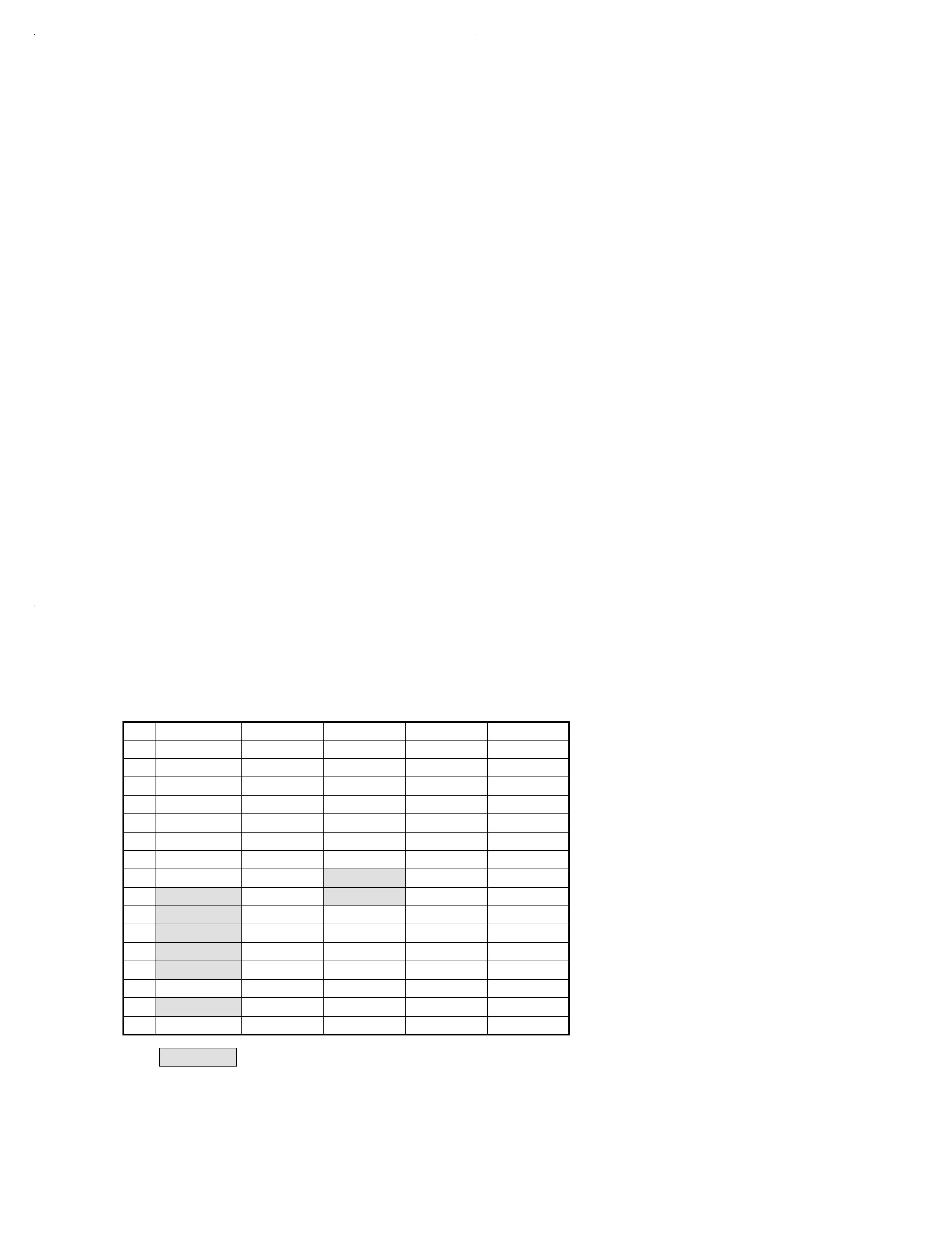
1-2. Test mode with serial communications
Refer to the test mode serial code table.
a) Setting procedure
· Plug the AC power cord and enter the TEST ON code.
8 bit serial communications
: 71H
16 bit serial communications
: 0C2FFH
b) Cancellation
· Enter the TEST OFF code (0CFEH) or unplug the AC
power cord.
c) Description
Other operations during the serial test mode
· The main unit's keys will be effective.
· The serial test code can be received even within 1 second
of POWER ON / OFF.
Required operations for the serial test mode
· The serial code for the serial test mode can be used to
check the operation of all circuits.
· The code entered during the serial test mode will become
valid regardless of the display mode.
· The following functions are available in the serial test
mode.
0 ~ 9, +10
AUTO (AUTO ST. / HI BLEND / MONO)
MEMORY
UP / DOWN (MANUAL SCAN unnecessary)
IF BAND, RF ATT
ACTIVE RECEPTION
ANTENNA A, ANTENNA B, PTY, DISPLAY, ALL LED
ON/OFF
· The MUTE signal is not output. This is for reducing the
input-output switching time during the measurement.
· When a valid serial code for the test mode is received, the
code identical to the code entered will be output.
· For checking the MUTE operation, MUTE has specific
codes.
MUTE ON/OFF
· To switch cyclically, enter the individual serial code. For
example for AUTO STEREO / MONO, enter the two
codes for AUTO STEREO and MONO.
· All the LEDs, turn ON / OFF is cancelled by inputting the
cancelling code and returned the LEDs to normal.
· All functions (including the test mode) will be initialized.
(K)KTF-20101P( 98.4.254:21PM y[W 7
background image
KTF-2010/3010
5
CIRCUIT DESCRIPTION
1-3. Initial settings
a) Setting procedure
· If the unit has a back-up function, hold down the POWER
key and plug the AC power cord.
· During the test mode with the main unit keys and the test
mode with serial communications, the initial settings can
be obtained by unplug and plug the AC power cord.
b) Description
· All function (including test mode) will be initialized.
· The manufacturer's memory is always set in the preset CH
and area.
1-4. POWER ON startup
· Since the unit has a POWER key, no setting is required.
1-5. Initial status
POWER ON/OFF
: OFF
TUNING MODE
: AUTO
PRESET MEMORY
: TEST FREQUENCY
LAST BAND
: FM
FM LAST FREQUENCY
: OVERSEAS 87.5MHz
/JAPAN 76.0MHz
AM.MW LAST FREQUENCY
: CH SPACE 9K 531kHz
: CH SPACE 10K 530kHz
LW LAST FREQUENCY
: 153kHz
LAST P.ch
: [--ch]
RDS DISPLAY MODE
: FREQUENCY DISPLAY
MODE
TA / NEWS / TA, NEWS
: OFF
ACTIVE RECEPTION
: OFF
ANT A/B
: A
IF BAND
: WIDE
RF ATT
: OFF
SERIAL
: XS8
1-6. Back-up status
POWER ON/OFF
TUNING MODE
PRESET MEMORY 1~40ch
LAST BAND
LAST P.ch
LAST FM FREQUENCY
LAST AM (MW) FREQUENCY
RDS AUTO MEMORY LIST
LAST LW FREQUENCY
ACTIVE RECEPTION
ANT A/B**
IF BAND**
RF ATT**
TA / NEWS / TA, NEWS*
PS STATION NAME*
* : E, T type
** : KTF-3010
8
9
A
.....
F
0
POWER OFF
0
MEMORY
1
POWER ON
1
2
MUTE OFF
2
3
MUTE ON
3
4
AUTO STEREO
4
5
MONO
5
PTY
6
6
DISPLAY
7
7
ATENNA A
8
Active reception OFF
8
ATENNA B
9
Active reception ON
9
All LED goes OFF
A
RF ATT OFF
+10
All LED goes ON
B
RF ATT ON
BAND FM
All LED ON : OFF
C
IF WIDE
BAND AM/MW
All LED ON :ON
D
BAND LW
HI BLEND
Initial setting
E
IF NARROW
TUNING DOWN
TEST OFF
F
TUNING UP
TEST ON
1-7. 16-bit serial test code (C2XXH)
: KTF-3010 ONLY
Note : Pls KT-2080/3080 service manual (B51-5128-00) on test frequency table and channel space table.
(K)KTF-20101P( 98.4.254:21PM y[W 10

Reviews

There are no reviews of this manual yet.